
Here is a solar charger circuit that is used to charge Lead Acid or Ni-Cd batteries using the solar energy power. It can charge a 6 volt 4.5 Ah rechargeable battery for various applications.
Features:
Solar Charger Circuit Diagram

The circuit uses a 12 volt solar panel and a variable voltage regulator IC LM 317. The solar panel consists of solar cells each rated at 1.2 volts. 12 volt DC is available from the panel to charge the battery. Charging current passes through D1 to the voltage regulator IC LM 317. By adjusting its Adjust pin, output voltage and current can be regulated.
VR is placed between the adjust pin and ground to provide an output voltage of 9 volts to the battery. Resistor R3 Restrict the charging current and diode D2 prevents discharge of current from the battery. Transistor T1 and Zener diode ZD act as a cut off switch when the battery is full. Normally T1 is off and battery gets charging current.
When the terminal voltage of the battery rises above 6.8 volts, Zener conducts and provides base current to T1. It then turns on grounding the output of LM 317 to stop charging.
Features:
- Voltage and Current regulation
- Over voltage cut off facilities
Solar Charger Circuit Diagram
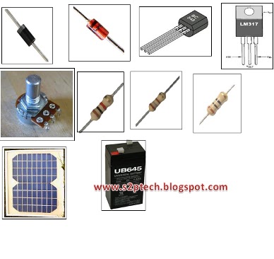
Main Parts used:
The circuit uses a 12 volt solar panel and a variable voltage regulator IC LM 317. The solar panel consists of solar cells each rated at 1.2 volts. 12 volt DC is available from the panel to charge the battery. Charging current passes through D1 to the voltage regulator IC LM 317. By adjusting its Adjust pin, output voltage and current can be regulated.
VR is placed between the adjust pin and ground to provide an output voltage of 9 volts to the battery. Resistor R3 Restrict the charging current and diode D2 prevents discharge of current from the battery. Transistor T1 and Zener diode ZD act as a cut off switch when the battery is full. Normally T1 is off and battery gets charging current.
When the terminal voltage of the battery rises above 6.8 volts, Zener conducts and provides base current to T1. It then turns on grounding the output of LM 317 to stop charging.


