Wish your computer had all the bells and whistles? You can get at least half-way there with this project, a USB-powered and -controlled bell that can be used for email notification or a manner of other things that require a satisfying "ding".
This project essentially consists of a microcontroller affixed inside the base of a counter bell, that pulls on the bell's clapper with an electromagnet, and communicates with the computer over USB. WAIT! COME BACK! Don't run away, I haven't told you how easy this project is yet!
This project is reasonably easy,
Here's a video of the bell in action, I am sending myself some emails, and as they appear in Thunderbird, the bell goes ding.
Some skills required:
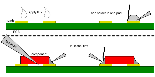
1. soldering - you'll need to solder just six electrical components together
2. electronics knowledge
3. knowledge of programming is entirely optional if you use the same microcontroller as I do since I've made all the code and firmware online so you can quickly download it and load onto the microcontroller over USB
Materials required (details to follow):
1. A counter bell of some sort with a steel clapper
2. A short bolt (to make a solenoid/electromagnet)
3. Some thin (less than 26 AWG) enamelled wire (about 2m)
3. A transistor
4. A resistor
5. A large capacitor (because USB probably won't supply enough power in one go to fire the electromagnet
6. A diode (flyback diode, as safety to avoid things blowing up)
7. A Forebrain (LPC1343 microcontroller) dev board (or you can use an alternative microcontroller/dev board if you want to have a go at coding it yourself)
8. Some prototyping board and wires
You will also need a soldering iron, some type of tape or adhesive to attach things to other things, and possibly some kind of cutting tool to cut a slot out of the base of the bell for the USB plug. And of course a computer (sorry, I only supply source and binaries for WIndows, the bell appears on a computer as a generic USB HID device, for which all modern operating systems have drivers built in for, so it would be relatively easy to code it for Linux or Mac).
Note: the bell does not check your email for you; you will need some sort of program on your computer to check your email and then activate the bell when you receive new mail. For Windows, the Thunderbird mail client works perfectly for this, or alternatively a utility called POP Peeper (more on this later).
Here is another video where I am triggering the bell manually from the computer. The bell plunger occasionally gets stuck, but I've since fixed that with some WD40.
WARNING: This project involves powering a home-made solenoid via the USB port, which may risk damage to your computer if your solenoid draws too much current. I highly recommend using a cheap powered USB hub. I accept no responsibility for any injury to you or damage to your equipment or property should you choose to attempt this. Please proceed AT YOUR OWN RISK.
This project essentially consists of a microcontroller affixed inside the base of a counter bell, that pulls on the bell's clapper with an electromagnet, and communicates with the computer over USB. WAIT! COME BACK! Don't run away, I haven't told you how easy this project is yet!
This project is reasonably easy,
Here's a video of the bell in action, I am sending myself some emails, and as they appear in Thunderbird, the bell goes ding.
Some skills required:
1. soldering - you'll need to solder just six electrical components together
2. electronics knowledge
3. knowledge of programming is entirely optional if you use the same microcontroller as I do since I've made all the code and firmware online so you can quickly download it and load onto the microcontroller over USB
Materials required (details to follow):
1. A counter bell of some sort with a steel clapper
2. A short bolt (to make a solenoid/electromagnet)
3. Some thin (less than 26 AWG) enamelled wire (about 2m)
3. A transistor
4. A resistor
5. A large capacitor (because USB probably won't supply enough power in one go to fire the electromagnet
6. A diode (flyback diode, as safety to avoid things blowing up)
7. A Forebrain (LPC1343 microcontroller) dev board (or you can use an alternative microcontroller/dev board if you want to have a go at coding it yourself)
8. Some prototyping board and wires
You will also need a soldering iron, some type of tape or adhesive to attach things to other things, and possibly some kind of cutting tool to cut a slot out of the base of the bell for the USB plug. And of course a computer (sorry, I only supply source and binaries for WIndows, the bell appears on a computer as a generic USB HID device, for which all modern operating systems have drivers built in for, so it would be relatively easy to code it for Linux or Mac).
Note: the bell does not check your email for you; you will need some sort of program on your computer to check your email and then activate the bell when you receive new mail. For Windows, the Thunderbird mail client works perfectly for this, or alternatively a utility called POP Peeper (more on this later).
Here is another video where I am triggering the bell manually from the computer. The bell plunger occasionally gets stuck, but I've since fixed that with some WD40.
WARNING: This project involves powering a home-made solenoid via the USB port, which may risk damage to your computer if your solenoid draws too much current. I highly recommend using a cheap powered USB hub. I accept no responsibility for any injury to you or damage to your equipment or property should you choose to attempt this. Please proceed AT YOUR OWN RISK.
Step 1Parts: The Bell

You'll need to get your hands on a bell of sorts. Most importantly, it needs to have a clapper that you can easily activate with an electromagnet. The one I purchased from eBay turned out to be absolutely perfect.
Pushing down on the top arm of the clapper would send the bottom half kicking out and striking the stainless steel bell. I figured I could place an electromagnet underneath top arm of the clapper and attract that downwards to ding the bell.
If your bell is different from this, you'll need to figure out a way to mount your electromagnet, and if the clapper isn't steel or iron, you may be able to get around it by affixing a magnet to the clapper and attracting/repelling that instead.
Step 2Parts: Electromagnet

You will need something to use as an electromagnet. I've found that winding your own solenoid coil using a short bolt and a length of copper wire is perfect for this.
Make sure that your electromagnet will fit in the space between the clapper and the base!
I used a spare steel bolt I found somewhere (thought it transpired that the bolt was not spare and was in fact the missing bolt from my chair), and wrapped about a meter and a half to two meters of enamelled copper wire onto it, using double-sided tape between the layers to ensure that they didn't slip off while I was winding the copper.
Without some archaic electromagnetism equations and careful measurement, it is difficult to predict how many turns of copper is required to make an adequate and safe solenoid/electromagnet. For this reason, I highly recommend testing the solenoid before using it, and finding the current draw if possible.
Just to reiterate in case you missed it at the first step: WARNING: This project involves powering a home-made solenoid via the USB port, which may risk damage to your computer if your solenoid draws too much current. I highly recommend using a cheap powered USB hub. I accept no responsibility for any injury to you or damage to your equipment or property should you choose to attempt this. Please proceed AT YOUR OWN RISK.
Step 3Parts: Electronics

You need four electrical components. I will be describing these very briefly, but ultimately I will have to leave it to you to make your own educated decisions on which components to use (or use exactly the same ones that I did).
A transistor
Choosing the right transistor for a project is a whole book in itself. Fortunately, for this project, most transistors with a pulse current rating of at least a few amps, and an hFE above 40 should probably work. I'm using a BDX53B Darlington transistor which I had lying around from other projects, it's not ideal, but it does the job. A TIP29 transistor would probably also work.
If you are using a MOSFET, you should add a pull-down transistor of about 1k after the gate resistor, otherwise the pull-up current of Forebrain in programming mode may be enough to fire the MOSFET.
If you don't know your transistors, I would suggest learning about how to choose the right transistor or asking someone about whether a certain transistor is suitable for this application or not before continuing, as the wrong choice might not work, damage something, or in the worst case blow up in your face.
A capacitor
A largeish aluminium electrolytic capacitor is required to supply some of the peak pulse currents required when the solenoid activates. The voltage rating must be above 5V, and I would recommend at least 470uF. I am using a 10V 2200uF capacitor
A diode
A diode is necessary to avoid flyback voltage spikes when the solenoid is switching. I'm using a 1N4004 general purpose diode
A resistor
Is needed to allow the microcontroller to drive the transistor. The value you should use depends on the the transistor you are using, if you don't know which resistor to use, I would suggest that 150ohms would probably work for most BJT devices, or 10ohms for a MOSFET. I am using a 150ohm resistor
Step 4Parts: Microcontroller

This bit is easy, I'm using a Forebrain dev board, which contains a 32-bit ARM Cortex-M3 microcontroller.
For those of you who don't know what microcontrollers are, they are little chips that can be programmed to carry out a whole number of things - from keeping time inside a digital watch, to running a microwave, to running your car. Forebrain is a development board carrying a microcontroller, it is designed so that you can easily use these useful little chips in your project without having to spend too much time soldering to impossibly small pins on the chip.
When you get a new Forebrain unit (the can be purchased from http://www.universalair.co.uk/ , they will be blank, and will not do anything useful. Software needs to be written and compiled (on a PC), and then downloaded onto the Forebrain unit before they start doing anything. The software that runs on microcontrollers is typically called "firmware", and the act of loading firmware onto a microcontroller is sometimes called "flashing", and has nothing to do with indecent exposure.
Because I've already written the software to make Forebrain act as a USB-controlled bell, you can simply download my compiled firmware (I'll tell you how later), and load it directly onto Forebrain over USB without ever having to look at a line of code. The whole process should take minutes, does not require any new software, and does not require you to learn any new skills or see a line of code.
Step 5Build: Install the stripboard


Ok, time to start building.
I cut down some stripboard in a rough circle, to fit into the space in the base of the bell. All the components will be soldered onto this circle of stripboard, and Forebrain will sit underneath it.
To secure it in place, I actually pushed some thumb tacks through the rivet holes in the bell base and into the pin holes on the stripboard and then soldered them in place (sorry, no photos of this, you'll notice the thumb tacks in later pictures). An alternative would be to use hot glue or epoxy resin.
Step 6Build: Install the electromagnet

Mount the electromagnet onto the stripboard somehow, and position it under the clapper so that there is enough room for the clapper to swing at the bell. If your solenoid is too long, you might have to cut a hole in the stripboard, if it's too short, you will had to add some spacers in there.
To secure it, hot glue or epoxy resin would be a good choice, I cut up some plastic, and used that to anchor mine down (didn't have any glue)
At this point, you could try to test to see the if the solenoid will pull the clapper down, you may need to screw the plunger in first otherwise the clapper will be too far away. Use a regulated power supply if you can (or one that won't be damaged if the solenoid draws too much current, three or four old alkaline AA batteries would work).
For the third time: WARNING: This project involves powering a home-made solenoid via the USB port, which may risk damage to your computer if your solenoid draws too much current. I highly recommend using a cheap powered USB hub. I accept no responsibility for any injury to you or damage to your equipment or property should you choose to attempt this. Please proceed AT YOUR OWN RISK.
Step 7Build: Install the other electronics


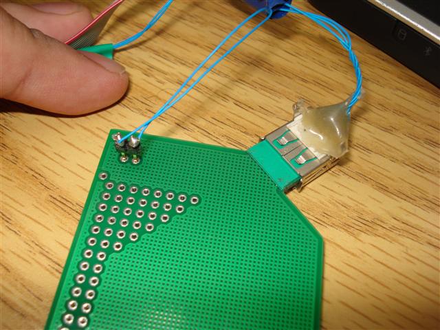
The three pins on the lower right of the Forebrain board is where you can get the GND and 5V supply from, and the firmware is set up to use Port 2, Pin 11 to drive the transistor. See the circuit diagram attached.
Careful of the polarity of the capacitor, and the pinout of the transistor!
Solder the other components in based on the circuit diagram. Make sure the bell does not touch any of the components when it is replaced. Bend the pins and install components horizontally if necessary
Careful of the polarity of the capacitor, and the pinout of the transistor!
Solder the other components in based on the circuit diagram. Make sure the bell does not touch any of the components when it is replaced. Bend the pins and install components horizontally if necessary
Step 8Build: Install Forebrain


A small gap needs to be cut into the base for the USB cable to pass through. I did this with a dremel, but feasibly you could use a file, or a small saw.
In my case I also ground down the front corners of Forebrain to fit the curvature of the base better. This isn't for the faint of heart to cut into your dev boards like that, but I can tell you with reasonable certainty that as long as you don't go too far, you won't hit anything vital (worst case is that the USB LED stops working).
Then solder the remaining wires connecting Forebrain to the board as per the circuit diagram in the previous page, there should only be three: 5V and GND from the USB, and Port 2 Pin 11 to the resistor.
Step 9Build: Flashing the Firmware


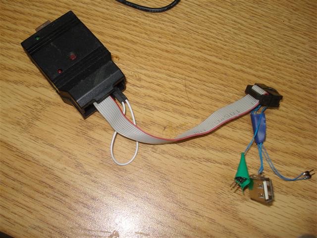
Now would be a good time to load the firmware onto Forebrain since you still have access to the buttons.
1. Gingerly connect the USB cable from Forebrain to the computer (Forebrain comes supplied with a retractable cable!). Make sure the solenoid hasn't come on, if it does, you will want to immediately disconnect the USB and check your circuits.
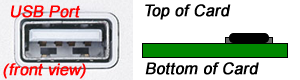
2. Once the USB is connected, and the solenoid hasn't come on, and nothing has broken, you can make Forebrain enter programming mode by holding down the button marked PRG while pressing the button marked RST (with the USB port facing upwards, PRG is on the left, the RST is on the right). You may need to do this twice for it to work.
3. If all goes well, the top-right LED on Forebrain should light up, and Forebrain will appear on your computer as a flash drive called "CRP DISABLED". Opening up this drive will reveal a single solitary "firmware.bin" file, delete this from the drive (you have to delete this otherwise the computer will complain about there not being enough space).
4. Download the firmware file that I wrote from: https://github.com/downloads/meseta/Ding-for-Forebrain/firmware.bin or alternatively if you want to play around with the code itself, you can find all the sources at https://github.com/meseta/Ding-for-Forebrain , Instructions on how to use Forebrain can be found at: http://www.universalair.co.uk/guides
5. Now drag this downloaded "firmware.bin" file into Forebrain's drive (the one called "CRP DISABLED"), if it complains about there not being any space, make sure the "firmware.bin" file already in the drive is deleted first.
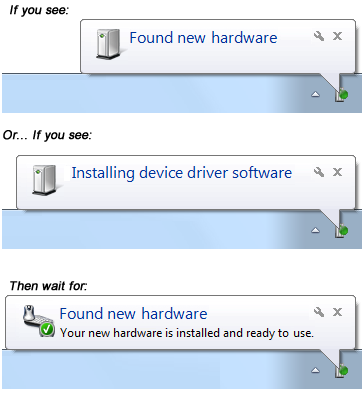
6. Once the file has copied, you can now unplug Forebrain, or hit reset (RST button). The next time you plug Forebrain into the computer (or press RST), Windows will recognise it as a "USB Input Device". Windows may attempt to search online for the drivers, before eventually realising that it actually already has them pre-installed. Forebrain is using a generic USB HID profile, so no special drivers are required.
1. Gingerly connect the USB cable from Forebrain to the computer (Forebrain comes supplied with a retractable cable!). Make sure the solenoid hasn't come on, if it does, you will want to immediately disconnect the USB and check your circuits.
2. Once the USB is connected, and the solenoid hasn't come on, and nothing has broken, you can make Forebrain enter programming mode by holding down the button marked PRG while pressing the button marked RST (with the USB port facing upwards, PRG is on the left, the RST is on the right). You may need to do this twice for it to work.
3. If all goes well, the top-right LED on Forebrain should light up, and Forebrain will appear on your computer as a flash drive called "CRP DISABLED". Opening up this drive will reveal a single solitary "firmware.bin" file, delete this from the drive (you have to delete this otherwise the computer will complain about there not being enough space).
4. Download the firmware file that I wrote from: https://github.com/downloads/meseta/Ding-for-Forebrain/firmware.bin or alternatively if you want to play around with the code itself, you can find all the sources at https://github.com/meseta/Ding-for-Forebrain , Instructions on how to use Forebrain can be found at: http://www.universalair.co.uk/guides
5. Now drag this downloaded "firmware.bin" file into Forebrain's drive (the one called "CRP DISABLED"), if it complains about there not being any space, make sure the "firmware.bin" file already in the drive is deleted first.
6. Once the file has copied, you can now unplug Forebrain, or hit reset (RST button). The next time you plug Forebrain into the computer (or press RST), Windows will recognise it as a "USB Input Device". Windows may attempt to search online for the drivers, before eventually realising that it actually already has them pre-installed. Forebrain is using a generic USB HID profile, so no special drivers are required.
Step 10Build: Finish the hardware

Once the hardware is loaded, you can install Forebrain more permanently (hot glue is a good choice). I have duct-taped mine since I plan on installing some LEDs as well (I will add steps to this instructable if I do).
You won't need access to the buttons again since I've thoughtfully added an extra command in the ding.exe to tell Forebrain to go back to programming mode.
Once you have plugged Forebrain in and it's recognised as a generic USB device, you can get the app that'll make the bell go ding from here: https://github.com/downloads/meseta/Ding-for-Forebrain/ding1.zip
Unzip this somewhere, you will get a ding.exe, and a dll file. Running the ding.exe program will send a signal to Forebrain to ding the bell. If something like this happens, then congratulations!
Step 11Configure (Optional)

If you hear some movement when you run ding.exe, but no ding, then you can try increasing the pulse time that drives the solenoid. To do this, ding.exe can be used to tune the signal time. Fire up a command line, navigate to where you are keeping ding.exe, and launch ding.exe with some parameters:
ding.exe 254 50
Will set forebrain to drive the solenoid with a 50ms pulse. Likewise, ding.exe 254 10 will use a 10ms pulse, and ding.exe 254 99 will use a 99ms pulse. The maximum pulse duration that can be set is 100ms to avoid drawing too much current from the USB port. Once you set the pulse duration, it is stored on Forebrain's EEPROM, so it will be remembered until you change it.
You can also tell Forebrain to re-enter programming mode by running ding.exe 255 , on receiving this command, Forebrain will disconnect itself from USB, wait a few seconds, and then reconnect in programming mode. After you load the firmware, you will want to hit RST, or if you can't reach that, simply unplug and replug the USB cable.
Step 12Configure: Email notifications with Thunderbird


Now that you have a USB controlled bell, you'll want to configure it to be used for something! Any program that'll let you run the ding.exe program as a method of notification will work.
For Thunderbird users, here are some instructions:
1. Download the FiltaQuilla extension, this will give you access to new filter options, including launching an application
2. Go to Tools>Message Filters
3. Create a new filter to match "Status is New" (and maybe also "Not Junk" would be helpful)
4. Set the perform actions to "Run file" (made available by the FiltaQuilla extension), and set the file to the ding.exe application.
5. Also remove the "@SUBJECT@,@MESSAGEID@" part that gets appended to the end of the ding.exe location
6. Repeat for other mail accounts if necessary
7. Sit back, and start sending yourself emails
Step 13Configure: Email notifications with POP Peeper


For those who don't use Thunderbird as a mail client, another option is to have a small utility like POP Peeper sit in your task tray checking your emails and launching ding.exe when it gets any new ones. POP Peeper supports IMAP.
POP Peeper has the ability to launch an "E-mail Client" when you get new mail. We will tell POP Peeper that ding.exe is an "E-mail Client" to make it do our bidding.
1. Download and install POP Peeper from http://download.cnet.com/POP-Peeper/3000-2369_4-10069858.html or http://www.poppeeper.com/ (don't forget to check the "SSL" option during install if you intend to connect to any mail servers via SSL or TLS)
2. Set up the mail accounts that you want to check (or import them).
3. If you're using IMAP, you can have it accept real-time (i.e. Push) email notifications by checking the "Use IDLE" in the account details, otherwise you can change the mail check period in the options.
4. In Options>General, set ding.exe as the email client
5. In Options>Noitification, set "When I receive new Email:" to "Run E-Mail Client"
6. Minimise, sit back and start sending yourself emails.
Step 14Links
Some links in previous steps all in one place:
Notification bell Firmware for Forebrain: https://github.com/downloads/meseta/Ding-for-Forebrain/firmware.bin
Bell trigger app for Windows: https://github.com/downloads/meseta/Ding-for-Forebrain/ding1.zip
Source code: https://github.com/meseta/Ding-for-Forebrain
Where to buy Forebrain: http://www.universalair.co.uk
How to use Forebrain: http://www.universalair.co.uk/guides
Thunderbird mail client: http://www.mozilla.org/thunderbird/
Filtaquilla plugin for Thunderbird: https://addons.mozilla.org/en-us/thunderbird/addon/filtaquilla/
POP Peeper utility: http://www.poppeeper.com/