Flash eight LEDs in Random manner


Flash LEDS            Flash LEDS Circuits        Flash eight LEDs in Random manner circuit Diagram

This project flashes eight LEDs in an apparently random manner. It uses a 4026 combined counter and display driver IC which is designed for driving 7-segment LED displays. The sequence is not really random because seven of the LEDs would normally be the display segments, the eighth LED is driven by an output that is normally used for driving further counters. The table below shows the sequence for the LEDs. You can use less than eight LEDs if you wish and the table may help you decide which ones to use for your purpose.

This project uses a 555 astable circuit to provide the clock pulses for the 4026 counter. Resistors are not required for the LEDs because the 4026 IC limits the current to about 5mA for each LED.

Parts Required

  • Resistors: 10k, 47k
  • Capacitor: 1µF 16V radial
  • LED: 3mm or 5mm LEDs ×8, they can be various colours
  • IC: 555 timer IC
  • IC: 4026 counter and display driver IC
  • DIL sockets for ICs: 8-pin, 16-pin
  • Battery clip for 9V PP3
  • Stripboard: 16 rows × 14 holes


Stripboard Layout


Circuit diagram


Flash LEDS            Flash LEDS Circuits        Flash eight LEDs in Random manner circuit Diagram


Read More

How to put Google Adsense below post title


1.) If you want to show your Google Adsense ad below post title to blogger in the left side then copy the below code

<div style="float: left; margin: 10px 10px 10px 0;">


YOUR ADSENSE CODE HERE
</div>
Code 1

OR

2.) If you want to show your Google Adsense ad below post tile to blogger in the right side then copy the below code

<div style="float: right; margin: 10px 0px 10px 10px;">


YOUR ADSENSE CODE HERE
</div>

Code 2

OR


3.) If you want to show your Google Adsense ad below post tile to blogger in the center then copy the below code

<div style="text-align: center; margin: 10px 10px 10px 0;">


YOUR ADSENSE CODE HERE
</div>

Code 3

Now You Have To Convert The Adsense Code Into Suitable Form

convert adsense code into suitable form HERE


Now where you have to paste this Code follow the below steps,

Sign in to Your Blogger Dashboard --> Design --> Edit HTML ( Expand Widget Templates ) find the code (using ctrl+F) <data:post.body/> and paste Your Code just before the <data:post.body/> code.

If you want to write your content below your Google Adsense Ad then also paste this code just below the Code 1 or Code2 or Code3 that is
<div style="clear:both"/>

If above methods are not working for you. Use following method

  • press CTRL + F to blogger search. Copy the following code and thrn paste this code to the search box to find the code block into your template starting from this line:
Code-block to find :-

  • Back to the AD converter and copy the converted code, by pressing the right mouse button and choose Select All again to continue copying.
  • Paste this code directly after the previous code block:

Paste Adsense Parse Code Here


  • Thats it. Enjoy blogging
Read More

Bihar Intermediate 2012 Results declared

Bihar Intermediate Results was declared on 5 June 2012 at 1:00 PM. Students are Searching for Their Results 2012 for 12th Class

Bihar Education Council for Intermediate of Science was Published 12th Check on – http://biharboard.net/interresult.html and http://results.indiaresults.com/Bihar/BIEC/2012/clsXII2012/rollquery.htm

Subscribe Free SMS Alert for Bihar Intermediate Results 2012. Subscriber will Get Free SMS on Mobile when Bihar Inter Results 2012 will be Published

Bihar Board 12th / Intermediate Results 2012 will be Published on Following Links

http://results.bihareducation.net/

http://biharboard.net/

Or,
Check Below:

Read More

How To Make PCB for USB Charger with MAX1811


Today i created pcb for Lithium Ion / Lithium Polymer USB Battery Charger with MAX1811, and designed with eagle pcb software.
About Max1811
The MAX1811 is a single-cell lithium-ion (Li+) battery charger that can be powered directly from a USB port or from an external supply up to 6.5V. It has a 0.5% overall battery regulation voltage accuracy to allow maximum utilization of the battery capacity.
The charger uses an internal FET to deliver up to 500mA charging current to the battery. The device can be configured for either a 4.1V or 4.2V battery. The MAX1811 is available in a small 1.4W thermally enhanced 8-pin SO package.


chargertoppusbcharger scheme 
P1060306 P1060313
P1060317 P1060319


Download: Eagle Files
Download PCB in: PDF 

Read More

How To Repair Laptop Battery


Laptop batteries can be one of the most frustrating parts of an older laptop. They differ from other types of batteries in that they provide a relatively short service life and are expensive to replace.

It must be remembered that most laptop batteries cannot be repaired if damaged. This is because of their complex construction. And even if it were to be repaired, one would need specific and expensive instruments to do so.

The battery has two parts, the chemical and the digital circuit. Chemical part can be restored with the risk of getting your files would be corrupted. It should be checked regularly for compatibility every time you use existing chargers. Batteries must also be kept alive with enough supply of voltage during cell replacements. Disconnecting the circuit, if only for a fraction of a second, can erase vital data and render the circuit unusable. To assure continued operation when changing the cells, connect a secondary voltage through a 100 Ohm resistor before disconnecting the cells. Always keep in mind to remove the secondary supply only after the circuit is fed with the needed operating voltage from the new cells.

Click here to see the rest of the project.
Read More

How To Make Traffic Light


This project operates red, amber and green LEDs in the correct sequence for a single UK traffic light. The time taken for the complete red - red & amber - green - amber sequence can be varied from about 7s to about 2½ minutes by adjusting the 1M preset. Some amber LEDs emit light that is almost red so you may prefer to use a yellow LED.

The 555 astable circuit provides clock pulses for the 4017 counter which has ten outputs (Q0 to Q9). Each output becomes high in turn as the clock pulses are received. Appropriate outputs are combined with diodes to supply the amber and green LEDs. The red LED is connected to the ÷10 output which is high for the first 5 counts (Q0-Q4 high), this saves using 5 diodes for red and simplifies the circuit.

This project uses a 555 astable circuit to provide the clock pulses for the 4017 counter.

Parts Required

  • Resistors: 470 ×3, 22k, 100k
  • Capacitors: 0.1µF, 1µF 16V radial, 10µF 16V radial
  • Diodes: 1N4148 ×6
  • LEDs: red, amber (or yellow), green
  • 1M preset, horizontal
  • 555 timer IC, such as NE555
  • 4017 counter IC
  • DIL sockets for ICs: 8-pin, 16-pin
  • On/off switch
  • Battery clip for 9V PP3
  • Stripboard: 20 rows × 21 holes


Stripboard Layout


Circuit diagram


Read More

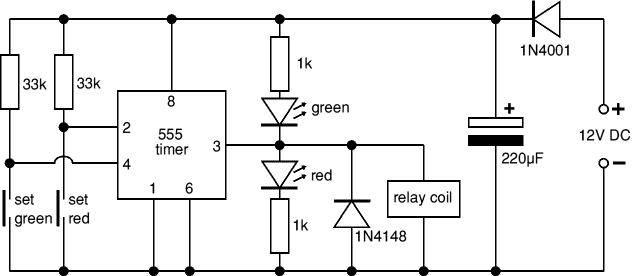
How To Make Model Railway Signal


A magnet under the train operates reed switches positioned on the track. The first reed switch changes the signal to red as the train passes, then further along the track a second reed switch changes the signal back to green ready for the next train. The isolated section of track just in front of the signal is switched off by the relay when the signal is red so a train will stop automatically at the red signal.

This project uses a 555 bistable circuit.


Parts Required:

Resistors:
1k ×2, 33k ×2
Capacitors:
220µF
Diode
1N4001 , 1N4148
LED
Red, Green (3mm best)
IC
555 timer
Socket
8-pin DIL for IC
Switch
Push-switch ×2
Switch
Reed switch ×2
Relay
SPCO 12V coil
Magnet

Miniature magnet each locomotive needs one
Stripboard
11 rows × 24 holes


Strip Board Layout:


Track connections:


  • Connect the reed switches to push-switches A and B (see the stripboard layout).
  • The switches can be held in place between the rails with a small piece of blu tac.
  • Connect the track wires to the COM and NC contacts of the relay.
  • When soldering to the track make sure you solder to the outside of the rail.
  • Each locomotive will need a miniature magnet glued to its underside - test first with blu tac, but superglue is probably best once you are sure it is in the correct position.
  • Note that railway signals have red at the bottom, unlike road traffic lights where red is at the top.


Circuit diagram:


Read More