How to block Pen drive in Computer


If you have windows XP with SP2, then you can disable the writing option to USB drives. This trick is very useful if you have virus in your computer and want to copy files from a USB Drive but don’t want to transfer virus to the USB. Follow the given steps to disable the USB writing option:

To edit the computer registry, first you should log onto your computer with administrative rights.
  • First click on Start button and type “Regedit” in Run option.

  • Here locate the location to:

HKEY_LOCAL_MACHINE\SYSTEM\CurrentControlSet\Contro l

  • Here in right side panel, click right to create a key with the name “StorageDevicePolicies”.


  • Now in left side panel, select “StorageDevicePolicies” key, again right click to create new DWORD value then label it “WriteProtect”. Set its value to “1″. But again to enable writing, set its values to “0″.


  • Now close the registry editor and restart your computer after any changes to go into effect.

Read More

How To Detect the use of Mobile phone in Examination Hall (Circuits)


This handy, pocket-size mobile transmission detector can sense the presence of an activated mobile phone from a distance of one and a-half metres. So it can be used to prevent use of mobile phones in examination halls, confidential rooms, etc. It is also useful for detecting the use of mobile phone for spying and unauthorised video transmission.


The circuit can detect both the incoming and outgoing calls, SMS and video transmission even if the mobile phone is kept in the silent mode. The moment the bug detects RF transmission signal from an activated mobile phone, it starts sounding a beep alarm and the LED blinks. The alarm continues until the signal transmission ceases.

An ordinary RF detector using tuned LC circuits is not suitable for detecting signals in the GHz frequency band used in mobile phones. The transmission frequency of mobile phones ranges from 0.9 to 3 GHz with a wavelength of 3.3 to 10 cm. So a circuit detecting gigahertz signals is required  for a mobile bug.

Here the circuit uses a 0.22μF disk capacitor (C3) to capture the RF signals from the mobile phone. The lead length of the capacitor is fixed as 18 mm with a  spacing of 8 mm between the leads to get the desired frequency. The disk capacitor along with the leads acts as a small gigahertz loop antenna to collect the RF signals from the mobile phone.

Op-amp IC CA3130 (IC1) is used in the circuit as a current-to-voltage converter with capacitor C3 connected between its inverting and non-inverting inputs. It is a CMOS version using gate-protected p-channel MOSFET transistors in the input to provide very high input impedance, very low input current and very high speed of performance. The output CMOS transistor is capable of swinging the output voltage to within 10 mV of either supply voltage terminal.

Capacitor C3 in conjunction with the lead inductance acts as a transmission line that intercepts the signals from the mobile phone. This capacitor creates a field, stores energy and transfers the stored energy in the form of minute current to the inputs of IC1. This will upset the balanced input of IC1 and convert the current into the corresponding output voltage.

Capacitor C4 along with high-value resistor R1 keeps the non-inverting input stable for easy swing of the output to high state. Resistor R2 provides the discharge path for capacitor C4. Feedback resistor R3 makes the inverting input high when the output becomes high. Capacitor C5 (47pF) is connected across ‘strobe’ (pin 8) and ‘null’ inputs (pin 1) of IC1 for phase compensation and gain control to optimise the frequency response.

When the mobile phone signal is detected by C3, the output of IC1 becomes high and low alternately according to the frequency of the signal as indicated by LED1. This triggers monostable timer IC2 through capacitor C7. Capacitor C6 maintains the base bias of transistor T1 for fast switching action. The low-value timing components R6 and C9 produce very short time delay to avoid audio nuisance.

Assemble the circuit on a general purpose PCB as compact as possible and enclose in a small box like junk mobile case. As mentioned earlier, capacitor C3 should have a lead length of 18 mm with lead spacing of 8 mm. Carefully solder the capacitor in standing position with equal spacing of the leads. The response can be optimised by trimming the lead length of C3 for the desired frequency. You may use a short telescopic type antenna.

Use the miniature 12V battery of a remote control and a small buzzer to make the gadget pocket-size. The unit will give the warning indication if someone uses mobile phone within a radius of 1.5 metres.
Read More

How To Make Ultrasonic Transmitter and Receiver


Most ultrasonic transmitters and receivers are built around timer IC 555 or complementary metal-oxide semiconductor (CMOS) devices. These devices are preset-controlled variable oscillators. The preset value of the working frequency is likely to drift due to mechanical vibrations or variations in temperature. This drift in frequency affects the range of transmission from the ultrasonic transducer.

The ultrasonic transmitter and receiver circuits described here use CD4017 decade counter ICs.

The transmitter circuit (Fig.1) is built around two CD4017 decade counter ICs (IC1 and IC2), D-type flip-flop IC CD4013 (IC3) and a few discrete components. The arrangement generates stable 40kHz signals, which are transmitted by transducer TX.


Fig.1: Transmitter circuit

The crystal-controlled radio-frequency (RF) oscillator built around  transistor T 1 (BC549) generates an 8MHz signal, which serves as input to the first decade counter built around IC1. The decade counter divides the oscillator frequency to 800 kHz. The output of IC1 is fed to the second CD4017 decade counter (IC2), which further divides the frequency to 80 kHz.

The flip-flop (IC3) divides 80kHz signal by 2 to give 40kHz signal, which is transmitted by ultrasonic transducer TX.

Coil L is made with 36SWG enamelled copper wire that is wound 15 times around an 8mm-diameter plastic former as used for radio oscillators, which has a ferrite bead.

The transmitter circuit works off 9-12V DC.

The receiver circuit (Fig.2) is built around a single decade counter CD4017 (IC4) and a few discrete components. To check the working of the transmitter, it is necessary to down-convert the 40kHz signal into 4kHz to bring it in the audible range. By using the receiver, the 40kHz ultrasonic transmitter can be tested quickly. The receiver’s transducer unit (RX) is kept near the ultrasonic transmitter under test. It detects the transmitted 40kHz signal, which is amplified by the amplifier built around transistor BC549 (T2). The amplified signal is fed to decade counter IC4, which divides the frequency to 4 kHz. Transistor T3 (SL100) amplifies the 4kHz signal to drive the speaker.


Fig.2: Receiver circuit

Use a 9V PP3 battery to power the receiver circuit.

House the transmitter and receiver circuits in separate small cabinets. If the 40kHz transducer under test is working, the receiver circuit produces audible whistling sound.
Read More

How To Make Magic Lights


The circuit as shown in the figure employs 14 bi-colour (red and green) LEDs having three terminals each. Different dancing colour patterns are produced using this circuit since each LED can produce three different colours. The middle terminal (pin 2) of the LEDs is the common cathode pin which is grounded. When a positive voltage is applied to pin 1, it emits red light. Similarly, when positive voltage is applied to pin 3. it emits green light. And when positive voltage is simultaneously applied to its pins 1 and 3, it emits amber light. The circuit can be used for decorative lights.


IC1 (555) is used in astable mode to generate clock signal for IC2 and IC3 (CD4518) which are dual BCD counters. Both counters of each of these ICs have been cascaded to obtain 8 outputs from each. The outputs from IC2 and IC3 are connected to IC4 through IC7 which are BCD to 7-segment latch/decodor/driver ICs. Thus we obtain a total of 14 segment outputs from each of the IC pairs consisting of IC4 plus IC5 and IC6 plus IC7. While outputs from former pair are connected to pin No. 1 of all the 14 bi-colour LEDs via current limiting resistors, the ouputs of the latter pair are similarly connected to pin No.3 of all the bi-colour LEDs to get a magical dancing lights effect.
Read More

Home automation Server with Router and Microcontroller

Turn a cheap router into a home automation server!

This project will allow you to switch outlets/lights from your iPhone, or any browser. You will also be able to send out serial commands remotely.

This project is based on SmartLinc.
http://www.smarthome.com/2412N/SmartLinc-INSTEON-Central-Controller/p.aspx
http://wiki.smarthome.com/index.php?title=2412_Manual_rev_2.0

Components
• OpenWRT compatible router, with serial header
• AVR microcontroller Development Board (like Arduino)
• Actuators like: RF switched outlets (433.92Mhz) with a remote

Step 1 : Overview 


Step 2:  The System


The Router runs a web server, you access it via browser. After you push a button on the web page the router sends out a serial command, we process this with a microcontroller, the AVR converts it to RF protocol, injects it into the RF remote, which controls the RF outlets.


Buy a router, listed here:http://wiki.openwrt.org/toh/start
I chose the TP-Link TL-WR741ND, because it is cheap (~$30).
Disassembly it (this will void the warranty!). You will have to solder a serial header to the circuit board, to gain access to the serial port.
The TL-WR741ND instructions can be found here:http://wiki.openwrt.org/toh/tp-link/tl-wr741nd.
For other routers, search here:http://wiki.openwrt.org/toh/start

After finished soldering, manage the four cables out of the case, through the vent holes. I used a RJ22 plug at the end, for rapid connection.

Step 3:  Configure the Router 


Install the Linux based OpenWRT firmware on the router. The TL-WR741ND instructions can be found here: http://wiki.openwrt.org/toh/tp-link/tl-wr741nd
If you are stuck, start here: http://openwrt.org

After you have a working SSH connection you can proceed.
Because of the router (by default) runs the web admin page on the port 80, we need to add a secondary port to serve our custom web site. For that, we need to configure the uhttpd (web server application) configuration file.

Download WinSCP, to simply do this through SSH. http://winscp.net/download/winscp429.zip

Set up a new connection:

  • Host name: normally 192.168.1.1 (by default)
  • Port: 22
  • User name: root
  • Password: what you gave after installation
  • File protocol: SCP

Find this file: /etc/config/uhttpd
Copy the following into it:
config 'uhttpd' 'secondary'
option 'listen_http' '81'
option 'home' '/HomeAutomation/www'
option 'cgi_prefix' '/cgi-bin'
option 'script_timeout' '60'
option 'network_timeout' '30'
And save it.

Step 4:  Setup the web page

  • Upload the /HomeAutomation/ folder structure into the root directory.
  • Set permissions for the script files located here: /HomeAutomation/www/cgi-bin
  • Select all of them -> F9 Properties -> set the execution rights (X) for everyone (Owner, Group, Others)
  • Close WinSCP, restart router (e.g. recycle power).
  • Now the web server is ready. Try it out:
  • Open up a web browser, type in: http://192.168.1.1:81
  • You should see your custom web page.

If you press a button on the included web page, the router will send out serial commands through the previously attached serial cable.
We need to intercept these commands and process them. For that purpose we need to build a microcontroller board (like Arduino).

The included web site is very basic. If you make good CGI/AJAX based web sites please share it with us.

How does the web site work
When you click on a button, the browser loads a script file, the router executes the shell commands (serial outputs) located in each cgi file. The script file then redirects the browser back to the index page (takes about ~1sec).

If you want to output custom serial commands, modify the .cgi files. Serial commands are sent out like this:
echo -e "\x9B\x11\x08\x22\xC5\x0D" > /dev/ttyS0
(the \x modifier is used to output data in HEX instead of ASCII)

Protocol detail
I made this simple as possible. One package contains:

Byte# Function:
1. Synchronization (0x9B)
2. Message type, use 0x00 or 0x01 for now (check firmware for details)
3. Data1
4. Data2
5. Checksum (calculated from Byte#2-4)
6. End character (0x0D)

HomeAutomation web page.zip
Packet Generator.xls

Step 5:  Hardware


For me the Atmega88 (with internal 8Mhz oscillator) failed to run on 3V3 (supplied by the router), so I had to include an external power supply, with 5V.

Because of that, we need to make a voltage conversion between the
5V MCU <-> 3V3 Router serial.
This PSU also has a 12V rail for the RF remote control, so it can run without battery.

Signal injection into RF remote controller
You need to find your own remote control's data path, normally it is between the IC and the transistor (see image). Use a resistor for driving the transistor.

Firmware
Burn the firmware using:
http://www.atmel.com/forms/software_download.asp?family_id=607&fn=dl_AvrStudio4Setup.exe
http://sourceforge.net/projects/winavr/files/WinAVR/20100110/WinAVR-20100110-install.exe/download
http://electronics-diy.com/avr_programmer.php

MCU: ATMEGA88
Oscillator: internal 8Mhz
Clear DIV8 fuse!
Firmware included in zip file.
You are more than welcome to share your improvements on the software.
MCU M88 int8Mhz.zip
Remote Decoder PT2272.pdf
Remote Encoder HX2262.pdf
Schematic.pdf

Step 6:  More Technical Details

Commonly used ICs in the RF switched outlet and remote controls are:
The RF protocol is included in these datasheets.

The reaction time from pressing a button on the page to the serial output from the router is:
iPhone & wifi: 1sec
PC & LAN: instantaneous (~100mS)
The delay can be decreased by using an AJAX based web page .

Step 7:  What is gained?

• You get a linux based system, running your custom softwares 24/7 with a power consumption of only 4.5W.
• Connect an IP webcam, embed the video feed in web page
• Ability to send out custom serial commands to any external device.
(be aware of the 3V3 serial voltage levels, I would strongly advise you to use CD40106 as a buffer)
• In this application you are able to send out any possible RF commands (based on the RF protocol) to the receivers. (i.e. no limitations on button numbers on the remote control)

How stable is it?
The system will not miss any commands, thanks to the TCP/IP Internet protocol and to the sophisticated microcontroller firmware.

Further improvements:
Tap into the switched outlet's RF receiver, add a MCU, detect data pattern, output IR code and you will get an Internet based remote controlled, remote control :D

Write software for the router that can handle incoming serial data.
YES you will be able to Twitt from your router (e.g. power consumption reports from external measuring devices).
Or do old school things like SMS two way control, home alarm system, IR repeater (through web), scheduler program to automatically control things on time bases.

Here is the original SmartLinc web page (it uses AJAX, and runs on AVR web server!)
http://www.cocoontech.com/forums/index.php?autocom=downloads&showfile=71
This is a good way to start developing web pages. SmartLinc web pages by xlurkr.zip


Credit: http://mrx23dot.blogspot.in/
Read More

How To control electrical appliances by Clapping


A “Clapper” is a device that will turn on or off an AC appliance that is plugged into it, such as a lamp or fan when it “hears” you clap twice in approximate succession.


Pete has built a Clever Clapper with various task. If user claps twice within one second, the circuit toggles the lamp output. On becomes off and vice versa. If user clap three times within one second, the lamps begin dimming up and down via PWM until a fourth clap is detected or a one minute timeout occurs, whichever comes first. The brightness value is then stored and restored for subsequent toggling of the lights on/off with the two clap event. The project also has a relay output to turn on and off the moon lamp. To trigger this relay, user shines a laser beam at the circuit to toggle it. Laser beams begets moon beams.

The project uses electret mic to capture signal, LM358 Op-amp for amplification and comparator, ATtiny2313 as PWM generator and control relay. If you want to build this project you can download firmware and schematic here
Read More

Monitor Temperature and Humidity inside Home Remotely using Webserver and Microcontroller


[Illustration]

This project combines the SHT11 temperature and humidity sensor together with the ds18s20 temperature sensor.

The SHT11 is ideal for indoor use. It requires a short cable length between ethernet board and sensor. It can measure temperature and humidity. Both are very important factors to maintain a comfortable and healthy climate. Nobody wants mold in the building.

ds18s20 is a very good outdoor sensor. You can have a long cable (about 10m, 33foot) between sensor and ethernet board and the sensor is fairly robust with regards to water exposure. You should keep it dry but it will survive it case it gets accidentally rained on.

There is also a new feature: the possibility to export long term measurement data into a column separated values file (CSV file) for import into a spreadsheet.

The ds18s20 is a pure temperature sensor. The SHT11 is a combined temperature and humidity sensor. The SHT11 makes it possible to accurately calculate the dew-point. The dew-point temperature is the temperature to which the air must be cooled to reach saturation. When the temperature cools to the dew point, fog or dew can occur.

Example: In your bath room you measure 23'C and 61% humidity. The resulting dew point is about 15'C. If your window or wall temperature would be 15'C or less then it would become wet.

[circuit diagram]

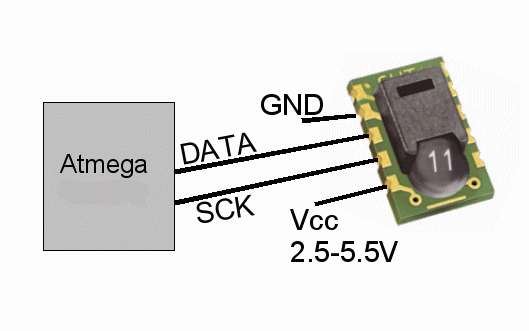
The above circuit diagram shows how to connect the sensors to the microcontroller on the ethernet board. The two sensors are fully digital and already calibrated. A pull-up resistor is required for the outdoor sensor if the cables length is above 2m (6foot). The resistor can be soldered onto the dotmatix field of the ethernet board. The pin-out of the two sensors is as follows.

[ds18s20]
The circuit allows also for the connection of a relay which can then be used to switch something remotely on or off (e.g the heating).


Cable length

This solution gives you a lot of flexibility. Ethernet cables can be very long (100m, 330ft). The board can therefore be located almost anywhere in the house. There should be a short cable between SHT11 indoor sensor and ethernet board (50cm, 1.6ft). A long cable can be used between the ds18s20 outdoor sensor and the ethernet board. A cable of 10m (33ft) has been used successfully for the outdoor sensor. A 10K pull-up resistor as shown in the above circuit diagram is recommended for an outdoor sensor cable length over 2m (6ft).


Connecting to the internet

The ethernet board provides a web server with the possibility to control the relay and read the sensors. To access it remotely over the internet you will need a DSL router with port forwarding. Most DSL routers can do that.

To know where your system is you will either need a static IP address or a DSL router that can work with dyndns.org. The best and most reliable solution is to use a static IP address. Many smaller internet service providers offer static IP addresses for a small additional fee. With tuxgraphics.org/cgi-bin/checkip you can see what your current IP address is. You can use this during initial testing while you do not yet have a static IP or a dyndns.org account.

You can have more than one of those boards connected to one DSL router. All you need to do is use different port numbers.

         Internal IP address and port    External URL
board 1: 192.168.0.4 port 80             http://my.summer.house/
board 2: 192.168.0.5 port 81             http://my.summer.house:81/

The web pages

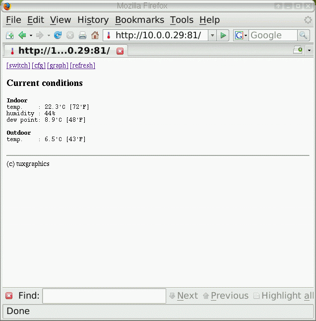
Here is what this solution looks like. The main window shows the current situation. On top is the menu to get to the other pages.


The relay control page allows you to switch on or off something using you password.

 [relay control page]

Clicking on "graph" takes you to a page where you can see historic data plotted as a bar-graph.

[historic data as bar graphs]

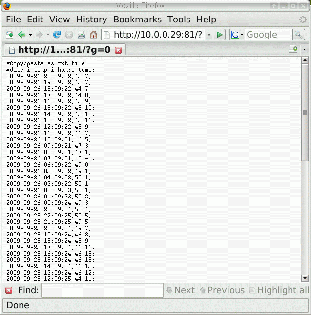
Clicking on "CSV data" you can get the historic data in column separated values format for import into a spreadsheet.


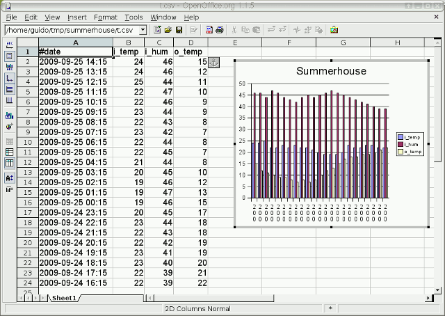
The data imported into a spreadsheet.


There is also a possibility to customize the recording interval. That is: the time periods at which samples are recorded as bar graphs and data for import into a spreadsheet.

As usual all the pages are designed to work as well on basic mobile data phones. This way you have also access when you are on the road.

 [on the mobile phone]

Download section 


Credit: http://tuxgraphics.org
Read More