Showing posts with label AVR. Show all posts

How To Make Brain Machine


The Brain Machine!


Relax and rejuvenate as your brain synchronizes to a wonderful meditative state, and enjoy as you hallucinate beautiful colors and patterns from your subconscious mind!

The Brain Machine provides you with a fun, easy way to meditate, all the while being very photogenic! They work with lights and sounds that pulse at a 14-minute-long meditation sequence of brainwave frequencies. Your brain synchronizes to this meditation sequence, and you meditate. It's that easy! And the beautiful colors and patterns you vividly imagine along the way make it fun and enjoyable.

Brain Machine by S2P Tech

Build your own Brain Machine to expand your brain's technical skills, then lean back and enjoy the light show. They are a blast at parties, a fun way to practice meditation and trip out.

The Brain Machine works with blinking lights. Be aware that blinking lights are not good for some people, especially those prone to seizures!
Read More:
Read More

How To Make Church bell Controller


Description
This circuit is a church bell controller. Basic component is an ATmega32 microcontroller. At the circuit 1 24LC32 eeprom memories is being used.

As control I created a menu who will be appeared on 4x20 LCD (Liquid Crystal Display). The menu browsing can be done by 6 buttons at the face of the circuit's box (Menu, Up, Down, Enter, Start, Stop). The all firmware binds about 30Kbytes flash memory and can be increased by adding new features-functions. This program has been written in C with CVAVR compiler.

The idea of this circuit is being given by a friend of mine who has an foundry and he is building bells. I have made the PCB by my self.


Features


1. More 75 different melodies (ADAM, PANYGJRJKO, AGJORJKO, etc)
2. Control of electrometrical clock of church with the production of pulse of duration 1Sec each one minute.
3. Automatic correction in case of power loss.
4. Percussion of clock each half but also entire hours, with possibility of choice of hours of silence (for tourist regions and hours of common quietness).
5. Manual correction of electromechanical clock.
6. All regulations become with the help of guidance (menu, up, down, enter, start, stop)
7. When it runs a rhythm we have the possibility of increase or decrease her speed, the information will stored in memory 24LC32.
8. Display time (DS1307), with backup battery.
9. All the in formations are displayed on 4X20 LCD.
10. Control up to 5 bells and 1 clock.
11. The user create his own program


Schematic


PCB


Photos


Photos


Improved version


Downloads


Improved version


Downloads

Read More

How to Interface Arduino with Visual Basic


I have tried VB2 and VB6. It is an easy environment for Hardware Engineers or Hobbyists to program. It means easy to code unlike C++. Programs made with the new VB may not be compact or fast; but as it runs on a Virtual DotNet Machine and is bug-safe and may not hang/boot too. The DotNet was MS answer to Java of Sun. Even Java is a simple language and it seems to be lighter too. DotNet of late has become a bigger download, more than 10 times the size it started with.

MS can try Visual Basic Webapp on the Cloud using HTML5. Even remotely hosted DotNet is better, with the VB Apps as Web Applications using DotNet WebService. Then nothing to download, neither the update or the security fixes. Just provide something like jQuery for DotNet. Web VB would be a better thing for developers.
Its possible, i have collected many WebApps here, Dact Apps – Web Applications for an Engineer or Hobbyist
Arduino is a QuickStart Embedded system, very useful in learning both the hardware and software elements of a system. “http://flakelabs.com/”>Michael of Flakelabs is started using the .Net Micro Framework. This is something like an OS for a
Small HandHeld Device.
4.1 release, the .NET Micro Framework enables developers to create powerful embedded systems that are more securely connected through a variety of wired and wireless protocols. The 4.1 release is also the first release under the Apache 2.0 license.
From what i understand, the developed app can be burned into the device fully, no additional layer of OS or Firmware needed, It is all built in. In short the compiled binary can be either a stand-alone firmware(OS) or be a layer running over a Mobile OS.
Now putting Ardunio and VB together, we get an Hardware/Software Environment that is easy on students and hobbyists too.


Fermata written by Andrew Craigie

Firmata is a generic protocol for communicating with microcontrollers from software on a host computer. It is intended to work with any host computer software package. See more examples ….

Arduino – Simple temperature monitor also see Visual C++ and Arduino

“Then for those that liked Java, He gave the Processing … thenceforward, the Inspired People made many Large Sketches and the Globe Glowed like Warm White LED Lamp”

(Processing is an IDE. It can also be used in Android mode, for that you will need Android SDK Installed.)

See this Steven’s Temperature Display and this Serial Comm using Processing. This compiles Java exe and Jar Applets. It can create programs for Windows, Linux and Mac.
Read More

Home automation Server with Router and Microcontroller

Turn a cheap router into a home automation server!

This project will allow you to switch outlets/lights from your iPhone, or any browser. You will also be able to send out serial commands remotely.

This project is based on SmartLinc.
http://www.smarthome.com/2412N/SmartLinc-INSTEON-Central-Controller/p.aspx
http://wiki.smarthome.com/index.php?title=2412_Manual_rev_2.0

Components
• OpenWRT compatible router, with serial header
• AVR microcontroller Development Board (like Arduino)
• Actuators like: RF switched outlets (433.92Mhz) with a remote

Step 1 : Overview 


Step 2:  The System


The Router runs a web server, you access it via browser. After you push a button on the web page the router sends out a serial command, we process this with a microcontroller, the AVR converts it to RF protocol, injects it into the RF remote, which controls the RF outlets.


Buy a router, listed here:http://wiki.openwrt.org/toh/start
I chose the TP-Link TL-WR741ND, because it is cheap (~$30).
Disassembly it (this will void the warranty!). You will have to solder a serial header to the circuit board, to gain access to the serial port.
The TL-WR741ND instructions can be found here:http://wiki.openwrt.org/toh/tp-link/tl-wr741nd.
For other routers, search here:http://wiki.openwrt.org/toh/start

After finished soldering, manage the four cables out of the case, through the vent holes. I used a RJ22 plug at the end, for rapid connection.

Step 3:  Configure the Router 


Install the Linux based OpenWRT firmware on the router. The TL-WR741ND instructions can be found here: http://wiki.openwrt.org/toh/tp-link/tl-wr741nd
If you are stuck, start here: http://openwrt.org

After you have a working SSH connection you can proceed.
Because of the router (by default) runs the web admin page on the port 80, we need to add a secondary port to serve our custom web site. For that, we need to configure the uhttpd (web server application) configuration file.

Download WinSCP, to simply do this through SSH. http://winscp.net/download/winscp429.zip

Set up a new connection:

  • Host name: normally 192.168.1.1 (by default)
  • Port: 22
  • User name: root
  • Password: what you gave after installation
  • File protocol: SCP

Find this file: /etc/config/uhttpd
Copy the following into it:
config 'uhttpd' 'secondary'
option 'listen_http' '81'
option 'home' '/HomeAutomation/www'
option 'cgi_prefix' '/cgi-bin'
option 'script_timeout' '60'
option 'network_timeout' '30'
And save it.

Step 4:  Setup the web page

  • Upload the /HomeAutomation/ folder structure into the root directory.
  • Set permissions for the script files located here: /HomeAutomation/www/cgi-bin
  • Select all of them -> F9 Properties -> set the execution rights (X) for everyone (Owner, Group, Others)
  • Close WinSCP, restart router (e.g. recycle power).
  • Now the web server is ready. Try it out:
  • Open up a web browser, type in: http://192.168.1.1:81
  • You should see your custom web page.

If you press a button on the included web page, the router will send out serial commands through the previously attached serial cable.
We need to intercept these commands and process them. For that purpose we need to build a microcontroller board (like Arduino).

The included web site is very basic. If you make good CGI/AJAX based web sites please share it with us.

How does the web site work
When you click on a button, the browser loads a script file, the router executes the shell commands (serial outputs) located in each cgi file. The script file then redirects the browser back to the index page (takes about ~1sec).

If you want to output custom serial commands, modify the .cgi files. Serial commands are sent out like this:
echo -e "\x9B\x11\x08\x22\xC5\x0D" > /dev/ttyS0
(the \x modifier is used to output data in HEX instead of ASCII)

Protocol detail
I made this simple as possible. One package contains:

Byte# Function:
1. Synchronization (0x9B)
2. Message type, use 0x00 or 0x01 for now (check firmware for details)
3. Data1
4. Data2
5. Checksum (calculated from Byte#2-4)
6. End character (0x0D)

HomeAutomation web page.zip
Packet Generator.xls

Step 5:  Hardware


For me the Atmega88 (with internal 8Mhz oscillator) failed to run on 3V3 (supplied by the router), so I had to include an external power supply, with 5V.

Because of that, we need to make a voltage conversion between the
5V MCU <-> 3V3 Router serial.
This PSU also has a 12V rail for the RF remote control, so it can run without battery.

Signal injection into RF remote controller
You need to find your own remote control's data path, normally it is between the IC and the transistor (see image). Use a resistor for driving the transistor.

Firmware
Burn the firmware using:
http://www.atmel.com/forms/software_download.asp?family_id=607&fn=dl_AvrStudio4Setup.exe
http://sourceforge.net/projects/winavr/files/WinAVR/20100110/WinAVR-20100110-install.exe/download
http://electronics-diy.com/avr_programmer.php

MCU: ATMEGA88
Oscillator: internal 8Mhz
Clear DIV8 fuse!
Firmware included in zip file.
You are more than welcome to share your improvements on the software.
MCU M88 int8Mhz.zip
Remote Decoder PT2272.pdf
Remote Encoder HX2262.pdf
Schematic.pdf

Step 6:  More Technical Details

Commonly used ICs in the RF switched outlet and remote controls are:
The RF protocol is included in these datasheets.

The reaction time from pressing a button on the page to the serial output from the router is:
iPhone & wifi: 1sec
PC & LAN: instantaneous (~100mS)
The delay can be decreased by using an AJAX based web page .

Step 7:  What is gained?

• You get a linux based system, running your custom softwares 24/7 with a power consumption of only 4.5W.
• Connect an IP webcam, embed the video feed in web page
• Ability to send out custom serial commands to any external device.
(be aware of the 3V3 serial voltage levels, I would strongly advise you to use CD40106 as a buffer)
• In this application you are able to send out any possible RF commands (based on the RF protocol) to the receivers. (i.e. no limitations on button numbers on the remote control)

How stable is it?
The system will not miss any commands, thanks to the TCP/IP Internet protocol and to the sophisticated microcontroller firmware.

Further improvements:
Tap into the switched outlet's RF receiver, add a MCU, detect data pattern, output IR code and you will get an Internet based remote controlled, remote control :D

Write software for the router that can handle incoming serial data.
YES you will be able to Twitt from your router (e.g. power consumption reports from external measuring devices).
Or do old school things like SMS two way control, home alarm system, IR repeater (through web), scheduler program to automatically control things on time bases.

Here is the original SmartLinc web page (it uses AJAX, and runs on AVR web server!)
http://www.cocoontech.com/forums/index.php?autocom=downloads&showfile=71
This is a good way to start developing web pages. SmartLinc web pages by xlurkr.zip


Credit: http://mrx23dot.blogspot.in/
Read More

How To control electrical appliances by Clapping


A “Clapper” is a device that will turn on or off an AC appliance that is plugged into it, such as a lamp or fan when it “hears” you clap twice in approximate succession.


Pete has built a Clever Clapper with various task. If user claps twice within one second, the circuit toggles the lamp output. On becomes off and vice versa. If user clap three times within one second, the lamps begin dimming up and down via PWM until a fourth clap is detected or a one minute timeout occurs, whichever comes first. The brightness value is then stored and restored for subsequent toggling of the lights on/off with the two clap event. The project also has a relay output to turn on and off the moon lamp. To trigger this relay, user shines a laser beam at the circuit to toggle it. Laser beams begets moon beams.

The project uses electret mic to capture signal, LM358 Op-amp for amplification and comparator, ATtiny2313 as PWM generator and control relay. If you want to build this project you can download firmware and schematic here
Read More

Monitor Temperature and Humidity inside Home Remotely using Webserver and Microcontroller


[Illustration]

This project combines the SHT11 temperature and humidity sensor together with the ds18s20 temperature sensor.

The SHT11 is ideal for indoor use. It requires a short cable length between ethernet board and sensor. It can measure temperature and humidity. Both are very important factors to maintain a comfortable and healthy climate. Nobody wants mold in the building.

ds18s20 is a very good outdoor sensor. You can have a long cable (about 10m, 33foot) between sensor and ethernet board and the sensor is fairly robust with regards to water exposure. You should keep it dry but it will survive it case it gets accidentally rained on.

There is also a new feature: the possibility to export long term measurement data into a column separated values file (CSV file) for import into a spreadsheet.

The ds18s20 is a pure temperature sensor. The SHT11 is a combined temperature and humidity sensor. The SHT11 makes it possible to accurately calculate the dew-point. The dew-point temperature is the temperature to which the air must be cooled to reach saturation. When the temperature cools to the dew point, fog or dew can occur.

Example: In your bath room you measure 23'C and 61% humidity. The resulting dew point is about 15'C. If your window or wall temperature would be 15'C or less then it would become wet.

[circuit diagram]

The above circuit diagram shows how to connect the sensors to the microcontroller on the ethernet board. The two sensors are fully digital and already calibrated. A pull-up resistor is required for the outdoor sensor if the cables length is above 2m (6foot). The resistor can be soldered onto the dotmatix field of the ethernet board. The pin-out of the two sensors is as follows.

[ds18s20]
The circuit allows also for the connection of a relay which can then be used to switch something remotely on or off (e.g the heating).


Cable length

This solution gives you a lot of flexibility. Ethernet cables can be very long (100m, 330ft). The board can therefore be located almost anywhere in the house. There should be a short cable between SHT11 indoor sensor and ethernet board (50cm, 1.6ft). A long cable can be used between the ds18s20 outdoor sensor and the ethernet board. A cable of 10m (33ft) has been used successfully for the outdoor sensor. A 10K pull-up resistor as shown in the above circuit diagram is recommended for an outdoor sensor cable length over 2m (6ft).


Connecting to the internet

The ethernet board provides a web server with the possibility to control the relay and read the sensors. To access it remotely over the internet you will need a DSL router with port forwarding. Most DSL routers can do that.

To know where your system is you will either need a static IP address or a DSL router that can work with dyndns.org. The best and most reliable solution is to use a static IP address. Many smaller internet service providers offer static IP addresses for a small additional fee. With tuxgraphics.org/cgi-bin/checkip you can see what your current IP address is. You can use this during initial testing while you do not yet have a static IP or a dyndns.org account.

You can have more than one of those boards connected to one DSL router. All you need to do is use different port numbers.

         Internal IP address and port    External URL
board 1: 192.168.0.4 port 80             http://my.summer.house/
board 2: 192.168.0.5 port 81             http://my.summer.house:81/

The web pages

Here is what this solution looks like. The main window shows the current situation. On top is the menu to get to the other pages.


The relay control page allows you to switch on or off something using you password.

 [relay control page]

Clicking on "graph" takes you to a page where you can see historic data plotted as a bar-graph.

[historic data as bar graphs]

Clicking on "CSV data" you can get the historic data in column separated values format for import into a spreadsheet.


The data imported into a spreadsheet.


There is also a possibility to customize the recording interval. That is: the time periods at which samples are recorded as bar graphs and data for import into a spreadsheet.

As usual all the pages are designed to work as well on basic mobile data phones. This way you have also access when you are on the road.

 [on the mobile phone]

Download section 


Credit: http://tuxgraphics.org
Read More

How To Control Remote application using Arduino Ethernet Shield


Ethernet Shield:


Arduino Ethernet shield V1.0

1. Schematic
The Arduino Ethernet Shield V1.0 is dedicated for the Arduino boards. It uses the Microchip's ENC28J60 SPI based stand-alone Ethernet controller (download datasheet here) and a compatible RJ45 socket with magnetics. Since the ENC28J60 is a 3V3 device that only drive 3V3 logic level output but capable of accepting 5V logic input, a 5V CMOS/TTL quad positive AND gates 74HCT08D is used to convert the 3.3 logic level output to 5V logic level.


Fig 1. Arduino Ethernet Shield schematic
2. Software Structure
The Ethernet Shield software is in the format of Arduino library, which you can download from here. The library is implemented based ontuxgraphics.org's open-source TCP/IP stack for Atmega88 and ENC28J60. The main files in the library are --
  • etherShield.cpp -- a wrapper cpp file, as an Arduino library interface with tuxgraphic's code
  • ip_arp_udp_tcp.c -- simplified TCP/IP stack implementation
  • enc28j60.c -- ENC28J60 SPI routines
  • net.h -- network protocol definitions
3. TCP/IP implementation
The standard TCP is a protocl to establish a connection. To do this, a number of packets needs to be exchaged between two sides first to establish the connection; then data packets can be exchaged. Usually a complicated state-machine is needed to implement the TCP protocol. 

For Auduino's ATMEGA168, a 8-bit AVR microcontroller with 1K SRAM, it is impossible to implement the full TCP stack. Also the webpage for 8-bit microcontroller that normally is used to control a relay or read a temperature sensor etc., is very simple. Therefore, instead of implementing full TCP protocl, a single data packet TCP protocol is used. You webpage contents, including all html tags, must be in one packet. The length of packet is limited by the SRAM size, currently half of the RAM space (500 bytes) is used for network Packet buffer. It is sufficient for simple webpages as shown below.

4. Ethersheild library installation & modification
First download the ethershield library here, then copy & unzip the library in your Arduino IDE library directory (for example arduino-0010/hardware/libraries/).
There are three examples in the ethershield library, you might need to change the ip address in the example sketch (.pde) files. The ip address must be a free address with your network range
static uint8_t mymac[6] = {0x54,0x55,0x58,0x10,0x00,0x24}; 

static uint8_t myip[4] = {192,168,1,15}; 

static char baseurl[]="http://192.168.1.15/"; 
 
Also you might like to change the webpage contents in the print_webpage funtion. Note that the webpage contents are stored in the PROGMEM (using PSTR declaration) to save the precious SRAM space.

uint16_t print_webpage(uint8_t *buf)

{

uint16_t plen;

plen=es.ES_fill_tcp_data_p(buf,0,PSTR("HTTP/1.0 200 OKrnContent-Type: text/htmlrnrn"));
... 
return plen;
}
 
Three examples are included in the ethershield library --
  • ethershield_ping.pde -- a PING example


    Ethernet ping 
  • ethershield_webserver.pde -- a general webserver example


    ethershield webserver 
  • ethershield_web_temperature.pde -- a webserver with temperature sensor (DS18B20) readings


    eth temperature 
  • ethershield_web_switch.pde -- New -- Webserver example, switch on/off LED


    ethershield webserver 
6. Links & Downloads
Read More

Thermal Datalogger: Collect thermal data in Laboratory


This is a simple datalogger developed mainly to collect thermal data in laboratory use, interfacing with LM35 sensors; normal voltage acquisition up to 20V is possible.Input selection between 20V, 2V, 0.2V can be done via jumper setting. A 7segment display let you control temperature in progress, while saving on internal eeprom let you have a log of the test. Eeprom content can be downloaded via a serial connection, the channel is a 5V-level RS232 to be connected to a usb to serial converter based on FT232 chip. Internal eeprom is used, but it's possible to add a 24c256eeprom ( yet not software supported ) Power supply can be from USB or external 5V.
Some pushbutton permit simple selectng of input and mode explained briefly in .c file.

Download Files:


Read More

Control and Maintain Temperature via Internet using Arduino


Equipped with Ethernet interface, Arduino controls a boiler to maintain the set temperature and publish environmental data via Internet on Pachube, and the web interface allows  setting the temperature  remotely via Internet.


The project is designed to control an heating system in order to keep the temperature in a room above a certain value, which can be set from Internet or a Personal Computer by LAN, because ours is not a simple thermostat but a complex unit managed by Arduino, which can connect to a local network with ethernet interface.  The thermostat allows many functions, including the publication  temperature measured at regular intervals (set by firmware), as well as the state of the boiler (on or off). The datas are published on the website http://www.pachube.com, which provides a database which stores user data, also makes available a series of gadgets to be able to view this data directly into web pages.


The Circuit

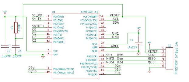
We start our description of the hardware on this card from the temperature sensor: it is a DS18B20 equipped with a logic that can express in binary format, two bytes, the temperature measured by its sensor element and the data on the surveys are made available through a serial communication channel called one-wire.
The Ethernet module is a WIZNET network adapter that can be interfaced via the SPI bus (Serial Peripheral Interface) 4-wire.
The module is a WIZ811MJ ethernet (IEEE 802.3/802.3) and W5100-based chip with full magnetic filters ethernet connector and 2 LEDs for status signaling. The module communicates with the microcontroller by SPI. It works with 3.3 Vcc and the 3V3 are provided by Arduino.
The connector J3 is that counts the largest number of connections: it comes from the control signal of the transistor T1, the controller of the relay RL1 (in parallel with the coil there is the LED LD2, signaling,  the excitement of the relay). Through J3 the Arduino reads status of buttons P1 and P2 and the input IN, all with pull-up resistor. The yellow LED LD1 is used to give the state mode or assist the setting of operation modes made with the P1 button. This allows you to choose between modes of operation of the system: sensor, manual or thermostat. Pressing once set the system in the sensor mode (automatic) and that this operation is indicated by a flashing dell’LD1, two pressures set the sistem in manual mode (command from web page), which is indicated by two flashes Led. Finally, three pressures set the system in thermostat mode (slave input IN), and this is communicated by three consecutive flashes dell’LD1. Pressing the button P1 returns the sistem in the first mode.
As for P2, currently not used and is reserved for future developments.


R1: 4,7 kohm
R2: 10 kohm
R3: 470 ohm
R4: 4,7 kohm
R5: 4,7 kohm
R6: 4,7 kohm
R7: 4,7 kohm
R8: 4,7 kohm
U1: WIZNET
U2: DS18B20
P1: Microswitch
P2: Microswitch
LD1: led 3 mm yellow
LD2: led 3 mm red
T1: BC547
RL1: Relé 5V
D1: 1N4007
- Screw connector 2 via
- Screw connector 3 via
- Strip male 6 via(2 pz.)
- Strip male 8 via (2 pz.)
- Strip female 10 via (4 pz.)
- PCB


How to use

Opening in the browser the thermostat IP address  (defined by the Arduino firmware) you can access the page and set the temperature of the system, the functions or active manually the boiler.
In the web page in memory dell’Arduino is also inserted a reference to the graphs of the gadget sites,  in the graph bottom of the page where you can choose which display period (from 1 minute to 1 year).
The web page contains the top, some buttons and boxes for the settings. There is a refresh button and below there are an indication of the status of the boiler (OFF or ON):  the system can be used for both heating systems both cooling and air conditioning: it depends on how connected the relay. In fact, with the exchange between C and NO it controls the boiler, while that between C and NC controls the air conditioner, this is because until the temperature is less than the threshold, the relay is energized and closes NO to NC, so it can turn on a boiler or other heating system, while when the temperature exceeds the set threshold, the relay returns to rest and NC close to C, going to control the cooling system.
We continue with the analysis of web page talking about the radio buttons under the present condition of the boiler, which are three and let you set how our system should work: clicking on the relay sensor is controlled based on temperature detected by the Dallas sensor, while opting for manual you can make the relay turn on and off using the On-screen buttons Boiler (relay activated), and Off Boiler (relay deactivated). Finally, opting for thermostat, the relay will be controlled according to the condition of our input IN interface card, this mode allows you to enslave the functioning of our system to an existing thermostat is substantially repeated in the environment and to relay the condition of the thermostat itself.
Below the radio buttons that define how, is the section of the temperature setting: Click in the box, you can set at will (within limits) the temperature at which the system should take, the setting made applies here by clicking the Set temperature.

We conclude the description of the web page with the chart, which summarizes the time courses of temperature measured by the sensor and the display may relate to a period of time to choose between 1 minute and 1 year.
As mentioned, the public system at that site www.pachube.com the value of the measured temperature, in a personal page reserved for each registered user, this site provides a service for storage and display of data from various sources, ranging from information gathered from sensors in environmental data, various measures, then everything is shared, or made accessible to registered users of the community.
In order to publish data on www.pachube.com you must first register and create an account, then take your chosen username and validated by the site and write in the special section of the firmware on the feed, without informing the user name of firmware, our system will not be able to access the site and publish the data.
Delivery of data for the upgrade can be done with a frequency set by firmware, bearing in mind the limits allowed by the site (about 50 accesses per hour) for obvious reasons, because if any application tries to access in real time site for uploading the data, at some point the bandwidth of the connection used by it and would soon be saturated with its server would have some problem to run.
Well, having said that we can conclude by pointing out that clicking on the word pachube that is below the temperature graph, you enter the page on www.pachube.com mail account used by the system to publish data on the page shown address of the corresponding link, containing the account name.


The Sketch
The sketch contains 3 .PDE files. This is the main program.

Download ZIP File Download the Thermostat sketch


Source Code:
/* Thermostat with arduino

 created 2011
 by Boris Landoni

 This example code is in the public domain.

http://www.s2ptech.blogspot.com

http://www.futurashop.it

 */

#include <SPI.h>
#include <Ethernet.h>
#include <avr/pgmspace.h>
#include <OneWire.h>
#include <DallasTemperature.h>
#include <EEPROM.h>
#define SHARE_FEED_ID              5102     // this is your Pachube feed ID that you want to share to
#define REMOTE_FEED_ID             256      // this is the ID of the remote Pachube feed that you want to connect to
#define REMOTE_FEED_DATASTREAMS    4        // make sure that remoteSensor array is big enough to fit all the remote data streams
#define UPDATE_INTERVAL            20000    // if the connection is good wait 10 seconds before updating again - should not be less than 5
#define RESET_INTERVAL             10000    // if connection fails/resets wait 10 seconds before trying again - should not be less than 5
#define PACHUBE_API_KEY            "xxxxxxxxxxxxxxxxxxxxxxxxxxxxxxxxx" // fill in your API key
#define ONE_WIRE_BUS 4
OneWire oneWire(ONE_WIRE_BUS);
DallasTemperature sensors(&oneWire);
DeviceAddress insideThermometer;

int puls1 = 5;                 // pulsante per il cambio di modalità di funzionamento
int puls2 = 2;                 // pulsante per il cambio di modalità di funzionamento
int in    = 3;                 // ingresso del termostato

prog_char string_0[] PROGMEM  = "<html><head><title>Boris's Project</title><META HTTP-EQUIV=\"Refresh\" CONTENT=\"3600\"></head>";
prog_char string_1[] PROGMEM  = "<body><center><br><form> <input type=button value=\"Refresh \" onClick=\"window.location.reload()\"> </form><br><br><h2>Remote Control Thermostat   ";
prog_char string_2[] PROGMEM  = " C</h2><form method=GET><font size= 5>Boiler ";
prog_char string_3[] PROGMEM  = "</font><br><font size= 3>Input Thermostat ";
prog_char string_4[] PROGMEM  = "</font><br><table><td><input type=\"radio\" name=\"statourl\" value=\"1\" onClick=\"this.form.submit()\"  ";
prog_char string_5[] PROGMEM  = "></td><td>Sensor</td><td><input type=\"radio\" name=\"statourl\" value=\"2\" onClick=\"this.form.submit()\" ";
prog_char string_6[] PROGMEM  = "></td><td>Manual</td><td><input type=\"radio\" name=\"statourl\" value=\"3\" onClick=\"this.form.submit()\" ";
prog_char string_7[] PROGMEM  = "></td><td>Thermostat</td><br></table> </form><form method=GET>";
prog_char string_8[] PROGMEM  = "<table><tr><td><input type=submit name=b11 value=\"Boiler ON\"></td><td><input type=submit name=b10 value=\"Boiler OFF\"></td><td>";
prog_char string_9[] PROGMEM  = "</td></tr></table></form><form method=GET>Temperature: <input type=\"text\" size=\"2\" name=temp value=#* MAXLENGTH=2>";
prog_char string_10[] PROGMEM  = "<input type=\"submit\" value=\"Set temperature\"><br></form>";
prog_char string_11[] PROGMEM = "<br><OBJECT classid=\"clsid:D27CDB6E-AE6D-11cf-96B8-444553540000\"";
prog_char string_12[] PROGMEM = "codebase=\"http://download.macromedia.com/pub/shockwave/cabs/flash/swflash.cab";
prog_char string_13[] PROGMEM = "#version=6,0,0,0\" WIDTH=\"200\" HEIGHT=\"100\" id=\"gauge\"><PARAM NAME=\"movie\"";
prog_char string_14[] PROGMEM = "VALUE=\"http://apps.pachube.com/scaredycat/gauge.swf?xml_source=";
prog_char string_15[] PROGMEM = "http%3A//apps.pachube.com/scaredycat/getData.php";
prog_char string_16[] PROGMEM = "%3Fm%3D0%26f%3D5102%26s%3D0%26u%3D30%26l%3D0%26n%3D5%26t%3D";
prog_char string_17[] PROGMEM = "Temperatura%26w%3Dfalse%26c1%3D33FF33%26c2%3DEFE415%26c3%3DEF8B15%26c4%3DFF3333%26";
prog_char string_18[] PROGMEM = "in%3Dtrue\" /><PARAM NAME=\"quality\" VALUE=\"high\" /><param name=\"wmode\" value=\"transparent\">";
prog_char string_19[] PROGMEM = "<param name=\"allowScriptAccess\" value=\"sameDomain\" /><EMBED src=\"";
prog_char string_20[] PROGMEM = "http://apps.pachube.com/scaredycat/gauge.swf?xml_source=";
prog_char string_21[] PROGMEM = "http%3A//apps.pachube.com/scaredycat/getData.php";
prog_char string_22[] PROGMEM = "%3Fm%3D0%26f%3D5102%26s%3D0%26u%3D30%26l%3D0%26n%3D5%26t%3D";
prog_char string_23[] PROGMEM = "Temperatura%26w%3Dtrue%26c1%3D33FF33%26c2%3DEFE415%26c3%3DEF8B15%26c4%3DFF3333%26in%3Dtrue\"";
prog_char string_24[] PROGMEM = "quality=\"high\" wmode=\"transparent\" WIDTH=\"200\" HEIGHT=\"100\"";
prog_char string_25[] PROGMEM = "NAME=\"gauge\" allowScriptAccess=\"sameDomain\" swLiveConnect=\"true\"";
prog_char string_26[] PROGMEM = "TYPE=\"application/x-shockwave-flash\" PLUGINSPAGE=\"";
prog_char string_27[] PROGMEM = "http://www.macromedia.com/go/getflashplayer\"></EMBED></OBJECT>";
prog_char string_28[] PROGMEM = "<br><br><script type=\"text/javascript\" src=\"http://www.google.com/jsapi\">";
prog_char string_29[] PROGMEM = "</script><script language=\"JavaScript\" src=\"http://apps.pachube.com/google_viz/viz_multi.js\">";
prog_char string_30[] PROGMEM = "</script><script language=\"JavaScript\">createViz([5102,5102],[0,1],800,400,[\"ff0000\",\"0000ff\"],0,40);</script>";
prog_char string_31[] PROGMEM = "";
prog_char string_32[] PROGMEM = "";
prog_char string_33[] PROGMEM = "<font size= 2>Powered by Open-Electronics.org - Boris Landoni</font>"; //please don't remove <img src="http://www.open-electronics.org/wp-includes/images/smilies/icon_smile.gif" alt=":-)" class="wp-smiley">
prog_char string_34[] PROGMEM = "";
prog_char string_35[] PROGMEM = "";
prog_char string_36[] PROGMEM = "";
prog_char string_37[] PROGMEM = "";
prog_char string_38[] PROGMEM = "";
prog_char string_39[] PROGMEM = "";
prog_char string_40[] PROGMEM  = "<br></center></body></html>";
prog_char string_41[] PROGMEM  = "<font color=\"red\">ON</font>";
prog_char string_42[] PROGMEM  = "OFF";
prog_char string_43[] PROGMEM  = "checked";
prog_char string_44[] PROGMEM  = "on";
prog_char string_45[] PROGMEM  = "off";

PROGMEM const char *string_table[] = // change "string_table" name to suit
{
string_0,
string_1,
string_2,
string_3,
string_4,
string_5,
string_6,
string_7,
string_8,
string_9,
string_10,
string_11,
string_12,
string_13,
string_14,
string_15,
string_16,
string_17,
string_18,
string_19,
string_20,
string_21,
string_22,
string_23,
string_24,
string_25,
string_26,
string_27,
string_28,
string_29,
string_30,
string_31,
string_32,
string_33,
string_34,
string_35,
string_36,
string_37,
string_38,
string_39,
string_40,
string_41,
string_42,
string_43,
string_44,
string_45
};

char buffer[150]; // make sure this is large enough for the largest string it must hold

byte mac[] = { 0xDE, 0xAD, 0xBA, 0xAF, 0xFA, 0xAD };
byte ip[] = { 192, 168, 0, 172 };
byte gateway[] = { 192, 168, 0, 1 };
byte subnet[] = { 255, 255, 255, 0 };
byte remoteServer[] = { 173,203,98,29 };            // pachube.com
float remoteSensor[REMOTE_FEED_DATASTREAMS];        // we know that feed 256 has floats - this might need changing for feeds without floats
String inString = String(35);
Server server(80);
const int led = 6;
const int rele = 7;
String temp="";
String statourl="";
int tam=0;
int st1=42,st2=42,st3=42,st4=42,st5=43,st6=44;
//float tempCold;
unsigned long pubblica;
unsigned long lampeggio;
int stato=1; // se 0 controllo con sensore temperatura integrato, se 1 controllo manuale, se 2 controllo con termostato esterno
float tempC=0;

void setup()
{
      pinMode(puls1, INPUT);
      pinMode(puls2, INPUT);
      pinMode(in, INPUT);
      pinMode(led, OUTPUT);
      pinMode(rele, OUTPUT);
      Serial.begin(9600);
      Ethernet.begin(mac, ip,gateway,subnet);
      server.begin();
      Serial.println("Serial READY");
      Serial.println("Ethernet READY");
      Serial.println("Server READY");
        sensors.begin();
        Serial.print("Found ");
        Serial.print(sensors.getDeviceCount(), DEC);
        Serial.println(" devices.");
        Serial.print("Parasite power is: ");
        if (sensors.isParasitePowerMode()) Serial.println("ON");
        else Serial.println("OFF");
        if (!sensors.getAddress(insideThermometer, 0)) Serial.println("Unable to find address for Device 0");
        Serial.print("Device 0 Address: ");
        printAddress(insideThermometer);
        Serial.println();
        // set the resolution to 9 bit (Each Dallas/Maxim device is capable of several different resolutions)
        sensors.setResolution(insideThermometer, 9);
        Serial.print("Device 0 Resolution: ");
        Serial.print(sensors.getResolution(insideThermometer), DEC);
        Serial.println();

}

// function to print a device address
void printAddress(DeviceAddress deviceAddress)
{
  for (uint8_t i = 0; i < 8; i++)
  {
    if (deviceAddress[i] < 16) Serial.print("0");
    Serial.print(deviceAddress[i], HEX);
  }
}

void printWebPage(Client *client)
{
    int tmp=0;
    int temperatura=0;
      // send a standard http response header
      client->println("HTTP/1.1 200 OK");
      client->println("Content-Type: text/html");
      client->println();

      strcpy_P(buffer, (char*)pgm_read_word(&(string_table[0]))); // Necessary casts and dereferencing, just copy.
      client->println( buffer );
      //Serial.println( buffer );
      for (int i = 1; i < 41; i++)
      {
          if (i==9)
          {
              strcpy_P(buffer, (char*)pgm_read_word(&(string_table[i])));  //butto tutto nell'array buffer
              for (tmp=0 ; tmp < sizeof(buffer); tmp++)
              {
                if (buffer[tmp]=='#')
                {
                  //Serial.println( "trovato ##### " );
                  temperatura = EEPROM.read(0);
                  Serial.print("dato in mem : ");
                  Serial.println(temperatura);
                  buffer[tmp] =  char ((temperatura/10)+48);
                  tmp++;
                  buffer[tmp] =  char ((temperatura % 10)+48);
                }

              }
          }
          else
          {
            strcpy_P(buffer, (char*)pgm_read_word(&(string_table[i]))); // Necessary casts and dereferencing, just copy.
          }
          client->println( buffer );

          switch(i){

              case 1:
                  itoa (tempC, buffer, 10); client->print( buffer ); Serial.print( buffer ); client->print( "," ); Serial.print( "," ); itoa ((int(tempC * 100) % 100), buffer, 10); client->print( buffer ); Serial.print( buffer ); break;
              case 2:
                  if(digitalRead(rele)) st4=41;
                  else st4=42;
                  strcpy_P(buffer, (char*)pgm_read_word(&(string_table[st4]))); client->println( buffer ); Serial.println( buffer ); break;
              case 3:
                  strcpy_P(buffer, (char*)pgm_read_word(&(string_table[st6]))); client->println( buffer ); Serial.println( buffer ); break;
              case 4:
                if (stato==1){
                  strcpy_P(buffer, (char*)pgm_read_word(&(string_table[st5]))); client->println( buffer ); Serial.println( buffer ); break;
                  }
              case 5:
                if (stato==2){
                  strcpy_P(buffer, (char*)pgm_read_word(&(string_table[st5]))); client->println( buffer ); Serial.println( buffer ); break;
                  }
              case 6:
                if (stato==3){
                  strcpy_P(buffer, (char*)pgm_read_word(&(string_table[st5]))); client->println( buffer ); Serial.println( buffer ); break;
                  }
          }
          delay(30);
      }

}

void verificaingressi()
{
  int temperatura = EEPROM.read(0);
  if (!digitalRead(puls1))
      {
        stato=stato+1;
        if (stato>3)
        {
          stato=1;
        }
       EEPROM.write(1, stato);
       digitalWrite(led,HIGH);
       delay(1000);
       digitalWrite(led,LOW);
       delay(1000);
       lampeggio=4000; //così lampeggia poi subito
      }

            if (stato==1)
      {
        if (tempC<temperatura )
        {
           digitalWrite(rele,HIGH);
           //st4=41;
        }
        else
        {
          if (tempC>(temperatura+1))
          {
            digitalWrite(rele,LOW);
            //st4=42;
          }
        }
      }

        if (!digitalRead(in))
        {
           if (stato==3) digitalWrite(rele,HIGH);
           st6=44;
        }
        else
        {
            if (stato==3) digitalWrite(rele,LOW);
            st6=45;
        }
}

void loop()
{

      stato = EEPROM.read(1);

      verificaingressi();
      sensors.requestTemperatures(); // Send the command to get temperatures

      tempC = sensors.getTempC(insideThermometer);
      if (millis() < pubblica) pubblica = millis();

      if ((millis() - pubblica) > UPDATE_INTERVAL){
          pubblica = millis();  

          Serial.println("Pubblico");
          Serial.print("Temp C    : ");
          Serial.println(tempC);
          if (tempC<50 && tempC>-20)
          {
            pachube_in_out(tempC);
          }
      }

      if (millis() < lampeggio)  lampeggio = millis();
      if ((millis() - lampeggio) > 5000){    //ogni 5 sec faccio lampeggiare il led giallo
          lampeggio = millis();
          for (int i = 0; i < stato; i++)
          {
                   //Serial.println("lamp");
                   digitalWrite(led,HIGH);
                   delay(250);
                   digitalWrite(led,LOW);
                   delay(250);
          }
      }

      Client client = server.available();

      int led=0;
      int tmp=0;
      if (client) {

      // an http request ends with a blank line
      boolean current_line_is_blank = true;
      while (client.connected()) {

      if (client.available()) {

      char c = client.read();
      if (inString.length() < 35) {
      inString.concat(c);

      }
      if (c == '\n' && current_line_is_blank) {

          if(inString.indexOf("b10")>=0){
            digitalWrite(led,LOW);
            stato=2;
          }
          if(inString.indexOf("b11")>=0){
            digitalWrite(led,HIGH);
            stato=2;
          }         

          if(inString.indexOf("b40")>=0){
            digitalWrite(led,LOW);
          }
          if(inString.indexOf("b41")>=0){
            digitalWrite(led,HIGH);
          }
          if(digitalRead(rele)) st4=41;
          else st4=42;  

          if (inString.indexOf("temp")>=0){
            char tempArr[20];
            temp=inString.substring(inString.indexOf('p')+2, inString.indexOf(" H"));
            temp.toCharArray(tempArr, 5);
            EEPROM.write(0, atoi(tempArr));
            tmp = EEPROM.read(0);
            stato=1;
          }

          if(inString.indexOf("statourl")>=0){
             char statoArr[20];
            statourl=inString.substring(inString.indexOf('l')+2, inString.indexOf(" H"));
            statourl.toCharArray(statoArr, 5);
            stato=(atoi(statoArr));
          }     

      EEPROM.write(1, stato);
      verificaingressi();
      printWebPage( &client);
      break;
      }
      if (c == '\n') {
      // we're starting a new line
      current_line_is_blank = true;
      } else if (c != '\r') {
      // we've gotten a character on the current line
      current_line_is_blank = false;
      }
      }
      }
      // give the web browser time to receive the data
      delay(1);
      inString = "";
      client.stop();
      }
}


Read More

How To Make Energy Meter Monitor using Arduino

This is a simple power meter to analize the current consuming in a house using the led indicator of a house energy meter.

Reading the red led of a home energy counters the system detects the corrent consumption in a house.

It is a noninvasive method, not cut wire, no current disconnects, so a very interesting method…
The system consists of two parts: the Arduino board that detects the led pulses and sends the data via the XBee module, and a PC that recive the data through a USB/Xbee module and processes the data with LabVIEW so you can prepare and study the consumption in a very instant.
Arduino sends two datas to the PC:
1 – Real time datas
2 – Average consumption measured in a time of 5 minutes.


 From the picture we see that the LED that indicates the current consumption is the red LED near to the display. In particular is the LED superior.

Arduino module
To detect the LED blinking you have to apply a simple photoresistor above the led and covered it with black tape. To read the analog voltage using the Arduino you have to use a resistive divider as shown in diagram:


The LED blinking causes the voltage drop down and this value is read by Arduino and compared with the voltage acquired by the potentiometer connected in the channel A0. This potentiometer has the task to adjust the sensitivity threshold.
The read data are processed from the sketch and then sends to the PC via Xbee module.

The Arduino code acquisition is as follows:
 delay(10); //10ms
   val_pot = analogRead(POT);
   delay(10); //10ms
   val_sensore = analogRead(SENSORE);
  if((val_sensore > val_pot)&(flag_acquire == 0)){
      flag_acquire = 1;
      digitalWrite(LED, LOW);
With this code Arduino acquires the two voltages, the photoresistor voltage compared with the voltage of the potentiometer, if the value is greater than the sketch actives the flag “flag_acquire = 1″, then read how much time has passed to another flash.
To do this use arduino to read a statement in an internal counter that returns the milliseconds since power on. The instruction is “millis ()” code here:
pre_tmS = cur_tmS;
      cur_tmS = millis();
      if( cur_tmS > pre_tmS ) {
        tm_diffS = cur_tmS – pre_tmS;
     }
There are 2 variables pre_tmS and cur_tmS, “cur_tmS” needs to read the current value of the internal counter: cur_tmS = millis (); Then if the condition (cur_tmS> pre_tmS) is true, I note the elapsed time between cycles, ie between the LED ON and the next cycle of the LED ON and write it on the variable “pre_tmS”. Now we have to send to the PC via the serial port using XBee with these instructions:
      Serial.print(“S”);
      Serial.println(tm_diffS);
      delay(10); //10ms
First Arduino sends a marker “S” used to labview to recognize that this value is part of the reading that real-time instant, then send the value in milliseconds elapsed. Now you have to reset the flag when the LED goes OFF using this statement:
  if((val_sensore < val_pot)&(flag_acquire == 1)){
      flag_acquire = 0;
     digitalWrite(LED, HIGH);
      impulsi++;      
      delay(10); //10ms
  }
You have to check the voltage acquired by the sensor, if it falls below the potentiometer value and the flag is active “flag_acquire == 1″ then you have to reset the flag. Note that the statement “impulsi++;” is simply a counter that counts the cycles of the LED power meter, this is to make an average energy consumed every 5 minutes. The third task is similar to the first task, wait 1 second, and increments the counter “time_flag++,” which is the fourth task of counting 300secondi (5 minutes). In addition, this task blinks the LED connected to pin 12 at a rate of 1 second.
The fourth task as mentioned above waiting 5 minutes and then sent via serial marker “L” is used to program labview to recognize that the data sent is the data on the average found in 5 minutes.

The sketch
#define POT 0
#define SENSORE 1
#define LED 13
#define LED1sec 12


// definire il tempo casuale che varia tra 40ms e 250ms
#define TimeAcquire  1000      //1sec
#define Time5Minuts  300      //5 minuti = 300sec


unsigned long cur_tm = millis();
unsigned long pre_tm = cur_tm;
unsigned int tm_diff = 0;


unsigned long cur_tmS = millis();
unsigned long pre_tmS = cur_tmS;
unsigned int tm_diffS = 0;


unsigned int time_flag=0;


unsigned int impulsi=0;
unsigned int val_pot=0;
unsigned int val_sensore=0;
char flag_acquire=0;
char flag_time=0;


void setup() {


  pinMode(LED, OUTPUT);
  pinMode(LED1sec, OUTPUT);
  Serial.begin(115200);          //  setup serial 115200
  Serial.println("ENEL KW/h reader!");


}


void loop() {


  //Acquisisco
   delay(10); //10ms
   val_pot = analogRead(POT);    // read the input pin
   delay(10); //10ms
   val_sensore = analogRead(SENSORE);    // read the input pin


  if((val_sensore > val_pot)&(flag_acquire == 0)){
      flag_acquire = 1;
      digitalWrite(LED, LOW);


      pre_tmS = cur_tmS;
      cur_tmS = millis();
      if( cur_tmS > pre_tmS ) {
        tm_diffS = cur_tmS - pre_tmS;
      }
      Serial.print("S");
      Serial.println(tm_diffS);


      delay(10); //10ms


  }
  if((val_sensore < val_pot)&(flag_acquire == 1)){
      flag_acquire = 0;
      digitalWrite(LED, HIGH);
      impulsi++;          //Incrementa impulsi
      delay(10); //10ms
  }


  //------Ogni 5 minuti invia "impulsi" ----------
  pre_tm = cur_tm;
  cur_tm = millis();
  if( cur_tm > pre_tm ) {
    tm_diff += cur_tm - pre_tm; //+=
  }
  if( tm_diff >= TimeAcquire ) { //Task ogni secondo
    tm_diff = 0;


    time_flag++;


    if(flag_time==0){
      digitalWrite(LED1sec, HIGH);
      flag_time = 1;
    }else{
      digitalWrite(LED1sec, LOW);
      flag_time = 0;
    }


  }


  if(time_flag>=Time5Minuts){


//Sono passati 5 minuti ? ..... Invia "impulsi" rilevati dal contatore
      Serial.print("L");
      Serial.println(impulsi);
      impulsi = 0;
      time_flag = 0;
  }


 //--------------------------------------------------


}

LABVIEW interface


To recive the data we use the XBee UartSbee V3.1 module from Futura Elettronica.


The interface created in LabVIEW is simple to use:


As can be seen from this figure, the top graph shows the average consumption every 5 minutes, while the bottom graph shows the real-time energy consumption. It ‘can save the data using the device as a data logger.
Read More