

ROBOTIC CAR
Robotic Car is a miniature prototype car powered by batteries whose various movements can be control either manually or automatically, or the combination of both. Here the command is given through keyboard; it would have been better if we used IR remote control or something of that kind rather than using keyboard for commanding. However, by realizing the complexities we have made simple using keyboard.
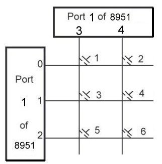
Block diagram of the project:

Some photographs of this model:


Project Description:
Keyboard section:
There are six switches in this section. They are
1: turn left.
2: turn right.
3: stop.
4: about turn.
5: park left.
6: park right.
Circuit diagram of keyboard is shown bellow.
Car section:
There are many sub sections in this section. They are
Motor:
We are using a 5V dc motor to drive the vehicle. The speed of the vehicle and its strength is controlled by the proper use of pulley. The rear wheel of the vehicle is connected to this motor through a pulley. This motor is meant for moving the vehicle both in forward and backward direction. Microcontroller (8051) controls the forward and backward movement of the vehicle in the following manner:

Here in the above circuit, T1, T2, T3, T4 are the NPN power transistor (2N3055). A0, A1, A2, A3 are the signals coming from the micro controller. With the specific combination of A0, A1, A2, A3 we can change the direction of rotation of motor as follows:
Case I:
When A0=high; A3=high; & A1=low; A2=low
The motor rotates in clockwise direction
Case II:
When A0=low; A3=low; & A1=high; A2=high
The motor rotates in anti-clockwise direction
Case III:
When A0=low; A3=low; A1=low; A2=low
The motor stops the rotation.
Stepper Motor:
A 5V dc Stepper motor is fixed at the front wheel lever directly. It enables the vehicle to rotate left or right through any angle. The electrical pulses generated from the micro controller directly control the movement of the stepper motor.
A stepper motor is an electromagnetic device that translates electrical pulses into mechanical movement.
Circuit diagram of keyboard is shown bellow. First 4 pins port 2 is connected to motor. Power transistors must be connected to drive the motor.

Transmitter and Receiver:
We are fitting three IR sensors along with the transmitter at the front of the vehicle in such an angle that the sensor will detect the signal only if certain obstacle is placed at the front of the vehicle at a distance of around 3 inches. This range of detection can be further adjusted by adjusting the amplitude of transmitter or by adjusting the angle of alignment between the transmitter and the sensor. All these sensors work independently and can sense the obstacle that comes at the front of the vehicle through different position independently. Thus with these three sensors, we are able to cover the entire frontal view of the vehicle at a distance of 3 inches. The circuit diagram of the transmitter and the receiver are given below:
Transmitter:
Transmitter circuit is used to transmit the IR rays. The IR LED emit infrared light switch is put on in the transmitting unit. To generate IR signal 555 IC based astable multivibrator is used. Infrared LED is driven through transistor BC 177.

Receiver:
The receiving unit consists of a sensor and its associated circuitry, which detects IR pulses transmitted by IR-LED. As a result the monostable is triggered and a short pulse is applied to port 2.5 of 8951. Circuit diagram is shown below. Do the same circuit two more times and connect it into 6 and 7 of port 2.
`

Working:
Manual mode:
In manual mode, the vehicle can be commanded through a wireless microphone to
1: turn left.
2: turn right.
3: stop.
4: about turn.
5: park left.
6: park right.
Turn left:
On getting the command of turn left, the vehicle turns towards left with 30 degree and after 3sec; it comes back to the original position. The degree in which the vehicle rotates, and the timing of coming back to the original position can be further adjusted based on our desired.
Turn right:
Right turn is same as that of left turn except for the fact that on getting command it turns towards right. All the modifications those are valid for the left turn is also true in this case.
Stop:
Once the vehicle gets the command for “stop” it remains in the idle state. There after its control is hand over to the beginning state.
About turn:
In about turn, the vehicle turns backward in two steps same as we did in our normal car. In first step the vehicle move only 90 degree and repeat the same in second step.
Park left:
On getting the command to park left, the vehicle parks on the left side of the road in a single step.
Park right:
Park right is same as that of park left, but here in this case, it parks towards the right side of the road.
You can also add two modes to the present design using two more switches. They are
Auto Mode:
In auto mode, the vehicle can be programmed to move at a particular place and park there. While moving, if any obstacle comes at the front of the vehicle, it will deviate its path automatically and come to the original path. The place where the vehicle is desired to move is the choice of the user; it can be either straight or bent path.
In our model, we have put three sensors at the front of the vehicle, so it is up to the user that, by what angle the vehicle should deviate. Further, it can be programmed on which side it should deviate, either left or right based on our desired. To alert the user that the vehicle is deviating an obstacle, a musical sound system is fitted in the vehicle, so that whenever it is deviating any obstacle, it will also play a music simultaneously.
Hybrid Mode:
It is the combination of both auto and manual mode. Here the vehicle can be commanded to move, to turn left or right. Further, while moving, if any obstacle comes on its path, it will deviate and come to its original path after deviating. However, if so happen that before coming to the original path, the sensor detects another obstacle; it will halt the movement of the vehicle, and play an alarm music as long as the obstacle is detected. The moment second obstacle is removed; the vehicle will continue its earlier execution.


