


This project is a RC quadrotor helicopter (quadrocopter, quadcopter, quadricopter, etc). It's a RC helicopter that uses 4 rotors.
Watch it in 720p
You need some pre-requisite skills:
When one rotor spins faster than the rotor on the opposing side, the faster side will have more lift, and thus the helicopter will tilt. When the helicopter is tilted, the air is being blown slightly sideways instead of directly down, and the helicopter will move.
The propellers also need to be in counter-rotating pairs, two spin clockwise and two spin counter-clockwise. This way, the helicopter does not spin on the vertical axis since the rotational enertia is cancelled out. But when the pair that's spinning in one direction is faster than the other pair, the helicopter will spin on the vertical axis. This is how the helicopter controls its direction.
We will be building a flight controller circuit that contains an accelerometer and gyroscope sensor so that a microcontroller can detect undesired changes in the helicopter's angle, and adjust each rotor's speed accordingly to counter the variation. This microcontroller will do this hundreds of times per second, keeping the helicopter stable in the air.
The flight controller is a completely open source circuit. The circuit schematic and PCB files are provided. The flight controller is completely Arduino compatible. The source code is a modified version of AeroQuad (open source Arduino based quadrocopter control code). The flight characteristics can be adjusted using AeroQuad's configurator utility.
Attached is a diagram that shows you the direction of spin for each motor, remember this diagram! You won't be able to fly if your setup does not follow this diagram.
This microcontroller will also take input from a RC radio receiver, so you can control the helicopter from the ground using a RC radio transmitter.
This helicopter will use four brushless motors. Each motor will be controlled by an ESC (Electronic Speed Controller). The ESCs will be controlled by the microcontroller.
A lithium polymer battery will power the entire contraption.
Summary of Downloads:
You need some pre-requisite skills:
- How to use Arduino, enough to get started
- Soldering, wiring, basic electronic skills
- Basic hand tool operation
When one rotor spins faster than the rotor on the opposing side, the faster side will have more lift, and thus the helicopter will tilt. When the helicopter is tilted, the air is being blown slightly sideways instead of directly down, and the helicopter will move.
The propellers also need to be in counter-rotating pairs, two spin clockwise and two spin counter-clockwise. This way, the helicopter does not spin on the vertical axis since the rotational enertia is cancelled out. But when the pair that's spinning in one direction is faster than the other pair, the helicopter will spin on the vertical axis. This is how the helicopter controls its direction.
We will be building a flight controller circuit that contains an accelerometer and gyroscope sensor so that a microcontroller can detect undesired changes in the helicopter's angle, and adjust each rotor's speed accordingly to counter the variation. This microcontroller will do this hundreds of times per second, keeping the helicopter stable in the air.
The flight controller is a completely open source circuit. The circuit schematic and PCB files are provided. The flight controller is completely Arduino compatible. The source code is a modified version of AeroQuad (open source Arduino based quadrocopter control code). The flight characteristics can be adjusted using AeroQuad's configurator utility.
Attached is a diagram that shows you the direction of spin for each motor, remember this diagram! You won't be able to fly if your setup does not follow this diagram.
This microcontroller will also take input from a RC radio receiver, so you can control the helicopter from the ground using a RC radio transmitter.
This helicopter will use four brushless motors. Each motor will be controlled by an ESC (Electronic Speed Controller). The ESCs will be controlled by the microcontroller.
A lithium polymer battery will power the entire contraption.
Summary of Downloads:
- Over 100 pictures in all the steps
- Step 9 contains flight controller circuit and PCB files
- Step 10 contains bootloader and core for microcontroller
- Step 12, 13, 14 contains demo Arduino sketches
- Step 26 contains the flight control software
Step 1Parts

RC radio transmitter and receiver
You need 4 channels minimum but I am begging you to get one with 6 channels. Also get one that uses 2.4 GHz technology if you can. Turnigy has a 9 channel model that is actually very inexpensive, and it runs on an AVR microcontroller that you can put custom firmware on. Personally, I have a old $25 radio that uses 75 MHz FM but I've converted it into a 2.4 GHz radio using a conversion kit.
Four brushless outrunner motors are needed. I used hexTronics 20-22L (this number represents the diameter and coil winding configuration of the motor, there's also a kv value that relates speed and power, higher kv = morepowerful faster motor (thanks to the correction from slick8086, I was incorrect to relate power to Kv, it's the RPM that's faster if Kv is higher), 800 to 1200 is acceptable motors. They come with a ton of parts (the bullet connectors, heatshrink, propeller adapter, the screws you need, mounting plate, spare shaft and spare C-clip, all included). Get extras just in case one gets damaged in a crash.
Four brushless motor electronic speed controllers (ESC) are needed. One that is rated for 18 amps is enough. I have heard good things about the Turnigy Plush ESCs because they support high update frequencies (more frequent adjustments means more stable flight). I got the HobbyKing brand clones of the Turnigy Plush ESCs because they are cheaper.
Some ESCs are "card programmable", meaning you can change their configuration using a cheap ($6)programming card, which is really convenient. Buy the programming card that is compatible with the ESCs you've chosen. I got the Turnigy ESC programming card because they are compatible with my ESCs.
You'll obviously need a battery. You will use a 3S1P lithium polymer battery that is rated at least 20C (this is the discharge rating). 3S means 3 cells in series, 1P means one set in parallel. This will give you a combined 11.1 volts. I suggest a 2500 mAH capacity battery (or more). A general rule of thumb is doubling the capacity of the battery means 50% increase in flight time (due to the extra weight).
More info on batteries here: http://www.rcgroups.com/forums/showpost.php?p=1315199&postcount=1
Make sure you pay attention to the type of connector that comes attached to your battery. You're going to need to get the matching connector. I've personally built my entire helicopter using bullet connectors.4.0mm bullet connectors for the battery and 3.5mm bullet connectors for everything else (the motors come with 3.5mm bullet connectors). (You can get other connectors such as XT-60 connectors, just watch your polarities, also note that all my pictures show bullet connectors)
You need a lot of heat-shrink tubing to act as insulation when using the 3.5mm bullet connectors. Get different colours so you can tell which wire is which.
You need 12 gauge stranded core wire. It must be 12 gauge or thicker to handle the current. It must be stranded core so that it is flexible. Get different colours so you know which wire is which polarity. The best wire is fine stranded copper wire with silicon insulation, but this is expensive.
Get a good battery charger, it must be able to balance and charge multi-cell lithium polymer batteries. I have one of these Turnigy chargers that have many settings, a LCD, and cooling fan, very nice. I also use a laptop power brick to power the charger since an ordinary wall adapter won't be able to handle the current required.
Get a battery monitor so you know when your battery is low. A lithium battery will become permanently damaged if you drain it below a certain threshold. Having a monitor will prevent you from damaging your battery. I have one of these that reports the status of each cell.
The quadcopter's frame I use is this one from HobbyKing. For $15, you get every part you need, plus every screw and nut you need. In comparison, a stick of aluminum would cost me $10 from Home Depot, which is not economical in comparison. I suggest you buy several frames so you have plenty of spare "arms" if you crash (plus plenty of spare screws and nuts).
The propellers must be in counter-rotating pairs (a "pusher" and a "puller"). I use 10x4.7 APC slow-fly propellers. 10 indicates diameter in inches and 4.7 indicates pitch. Larger diameter means more lift but requires more powerful motors. 10 inches is about right for the frame size I am using.
You'll need a entire flight controller circuit (meaning another entire bill of material), I will talk about this in detail later. Meanwhile, you'll need a USB-to-serial cable (FTDI cable) and an AVR programmer.
Plenty of servo cables are required to connect stuff. A minimum of 6 female-to-female cables is required for the 6 channels from the RC radio receiver to the flight controller.
Velcro tape and double sided velcro strapping will be useful as a lightweight way of mounting things and strapping in the battery.
Get a bubble/spirite level (like this one) to help with sensor calibration.
Make sure you get plenty of extras, stock pile on wire, cables, connectors, heat-shrink tubing, electrical tape, glue, screws, etc.
You need 4 channels minimum but I am begging you to get one with 6 channels. Also get one that uses 2.4 GHz technology if you can. Turnigy has a 9 channel model that is actually very inexpensive, and it runs on an AVR microcontroller that you can put custom firmware on. Personally, I have a old $25 radio that uses 75 MHz FM but I've converted it into a 2.4 GHz radio using a conversion kit.
Four brushless outrunner motors are needed. I used hexTronics 20-22L (this number represents the diameter and coil winding configuration of the motor, there's also a kv value that relates speed and power, higher kv = more
Four brushless motor electronic speed controllers (ESC) are needed. One that is rated for 18 amps is enough. I have heard good things about the Turnigy Plush ESCs because they support high update frequencies (more frequent adjustments means more stable flight). I got the HobbyKing brand clones of the Turnigy Plush ESCs because they are cheaper.
Some ESCs are "card programmable", meaning you can change their configuration using a cheap ($6)programming card, which is really convenient. Buy the programming card that is compatible with the ESCs you've chosen. I got the Turnigy ESC programming card because they are compatible with my ESCs.
You'll obviously need a battery. You will use a 3S1P lithium polymer battery that is rated at least 20C (this is the discharge rating). 3S means 3 cells in series, 1P means one set in parallel. This will give you a combined 11.1 volts. I suggest a 2500 mAH capacity battery (or more). A general rule of thumb is doubling the capacity of the battery means 50% increase in flight time (due to the extra weight).
More info on batteries here: http://www.rcgroups.com/forums/showpost.php?p=1315199&postcount=1
Make sure you pay attention to the type of connector that comes attached to your battery. You're going to need to get the matching connector. I've personally built my entire helicopter using bullet connectors.4.0mm bullet connectors for the battery and 3.5mm bullet connectors for everything else (the motors come with 3.5mm bullet connectors). (You can get other connectors such as XT-60 connectors, just watch your polarities, also note that all my pictures show bullet connectors)
You need a lot of heat-shrink tubing to act as insulation when using the 3.5mm bullet connectors. Get different colours so you can tell which wire is which.
You need 12 gauge stranded core wire. It must be 12 gauge or thicker to handle the current. It must be stranded core so that it is flexible. Get different colours so you know which wire is which polarity. The best wire is fine stranded copper wire with silicon insulation, but this is expensive.
Get a good battery charger, it must be able to balance and charge multi-cell lithium polymer batteries. I have one of these Turnigy chargers that have many settings, a LCD, and cooling fan, very nice. I also use a laptop power brick to power the charger since an ordinary wall adapter won't be able to handle the current required.
Get a battery monitor so you know when your battery is low. A lithium battery will become permanently damaged if you drain it below a certain threshold. Having a monitor will prevent you from damaging your battery. I have one of these that reports the status of each cell.
The quadcopter's frame I use is this one from HobbyKing. For $15, you get every part you need, plus every screw and nut you need. In comparison, a stick of aluminum would cost me $10 from Home Depot, which is not economical in comparison. I suggest you buy several frames so you have plenty of spare "arms" if you crash (plus plenty of spare screws and nuts).
The propellers must be in counter-rotating pairs (a "pusher" and a "puller"). I use 10x4.7 APC slow-fly propellers. 10 indicates diameter in inches and 4.7 indicates pitch. Larger diameter means more lift but requires more powerful motors. 10 inches is about right for the frame size I am using.
You'll need a entire flight controller circuit (meaning another entire bill of material), I will talk about this in detail later. Meanwhile, you'll need a USB-to-serial cable (FTDI cable) and an AVR programmer.
Plenty of servo cables are required to connect stuff. A minimum of 6 female-to-female cables is required for the 6 channels from the RC radio receiver to the flight controller.
Velcro tape and double sided velcro strapping will be useful as a lightweight way of mounting things and strapping in the battery.
Get a bubble/spirite level (like this one) to help with sensor calibration.
Make sure you get plenty of extras, stock pile on wire, cables, connectors, heat-shrink tubing, electrical tape, glue, screws, etc.
Step 2Bullet Connector Soldering


You'll be doing a lot of soldering, especially with these rather large connectors. I'm writing this section because of the special connectors we'll be using requires some special soldering techniques. There's a lot of current going through these wires, and they have to withstand crashes and you yanking on them. So you should do this properly.
You need a good hot soldering iron for this, since the connectors are rather large and act as a heatsink.
First, take a piece of wood, and drill some holes into it to hold your connector while you solder. This is your soldering jig.
Strip your wire, the length of exposed wire should be as long as the cavity in the connector's end. If you are soldering the 4mm connectors with the polarized housing, make sure the housing goes on first before you solder (see pictures).
Place the connector into the hole in the wood. Then stick your soldering iron's tip into the small hole on the side of the connector. Fill the cavity with solder (fill the cavity about 60%). While the solder is hot, put the wire into the cavity, continue heating for a few seconds until you are sure the wire has reached thermal equibrium with the solder, and then remove the iron. Hold the wire still until the solder cools and solidifies.
Wait until the entire connector is cool enough to touch. Clean the solder joint with rubbing alcohol.
If you are using the plastic housing, pull on the wire into the housing until the connector clicks into the housing. If you are not using the housing, then use heat-shrink tubing to insulate the connector. See pictures.
Also relevant links (not created by me):
Step 3Preparing the Motors


If you got the same motors that I did (hexTronics 20-22L), then you'll notice that the shaft sticks out the bottom of the motor. I cut this off with a cutoff-disk attached to a rotory tool. This is because I don't want the motor to be damaged from a minor bump with the ground.
When you are cutting off the shaft, make sure you first wrap the entire motor with tape first to prevent metal shavings and debris from entering the motor. Dust and debris can damage the windings and bearings. Also when you are done, thoroughly clean the motor by spraying it with compressed air.
Assemble the motor, attach the large propeller adapter, and the bottom mounting plate, using the appropriate screws that are provided.
The motors comes with 3.5mm bullet connectors and heat-shrink. Solder the male connectors to the motor. The female connectors are meant for the ESC (we'll do that later).
Step 4Understanding Brushless Motors


It is important for you to understand how brushless motors and ESCs work, so that you don't destroy your ESCs.
To reverse the direction of motor spin, DO NOT REVERSE THE POWER INPUT TO THE ESCs.
You'll note that there are three wires that goes between the motor and the ESC. These motors are three phase motors, meaning there are three coils inside. The coils are energized in sequence to make the motors spin. So the ESC's job is to energize the coils in sequence, but it needs to time each energization correctly so the motor can actually accelerate to the right speed. The ESC has a microcontroller inside that turns on or off the coils using FETs and also determines timing by measuring the feedback in the coils caused by the movement of the magnets.
Now you should understand that to reverse the direction of spin of the motor, you can swap any two of the three wires between the motor and ESC. To visualize this, if the original sequence was:
123123123123123
and we swap 2 and 3, we get:
132132132132132
and thus the direction of spin is reversed.
Also, the ESCs contains a 5V voltage regulator (most likely a cheap 7805), and a low battery cut-off feature. Our flight controller will use this 5V power supply.
The cut-off feature means when your lithium polymer battery is drained, it will stop spinning the motor to protect the battery. This is because permanent damage can occur to your battery if it is drained below a threshold. But when the motor stops spinning, the voltage regulator still provides the 5V. This is so that servos on an airplane can still function using that 5V supply, and the RC airplane can still glide to a safe landing even without an engine.
However, in our helicopter situation, if one motor dies, the helicopter will spin out of control in the air. It will become a safety hazard to everybody around it. Thus, we set the cut-off voltage to "low" so we maximize flight time. We rely on our battery monitor instead, so we avoid over-draining the battery.
A side note: some ESCs can be hacked! You like hacking, right? Read this: http://www.rcgroups.com/forums/showthread.php?t=766589 . The advantage of I2C controlled ESCs is higher update rates, more precision, and only takes two wires to control up to 127 motors. It'll take some small changes in the compilation options of our flight software to use them since the code is already available. However, for the rest of this instructable, I'm still using PWM controlled ESCs.
- http://en.wikipedia.org/wiki/Brushless_DC_electric_motor
- http://electronics.howstuffworks.com/brushless-motor.htm
To reverse the direction of motor spin, DO NOT REVERSE THE POWER INPUT TO THE ESCs.
You'll note that there are three wires that goes between the motor and the ESC. These motors are three phase motors, meaning there are three coils inside. The coils are energized in sequence to make the motors spin. So the ESC's job is to energize the coils in sequence, but it needs to time each energization correctly so the motor can actually accelerate to the right speed. The ESC has a microcontroller inside that turns on or off the coils using FETs and also determines timing by measuring the feedback in the coils caused by the movement of the magnets.
Now you should understand that to reverse the direction of spin of the motor, you can swap any two of the three wires between the motor and ESC. To visualize this, if the original sequence was:
123123123123123
and we swap 2 and 3, we get:
132132132132132
and thus the direction of spin is reversed.
Also, the ESCs contains a 5V voltage regulator (most likely a cheap 7805), and a low battery cut-off feature. Our flight controller will use this 5V power supply.
The cut-off feature means when your lithium polymer battery is drained, it will stop spinning the motor to protect the battery. This is because permanent damage can occur to your battery if it is drained below a threshold. But when the motor stops spinning, the voltage regulator still provides the 5V. This is so that servos on an airplane can still function using that 5V supply, and the RC airplane can still glide to a safe landing even without an engine.
However, in our helicopter situation, if one motor dies, the helicopter will spin out of control in the air. It will become a safety hazard to everybody around it. Thus, we set the cut-off voltage to "low" so we maximize flight time. We rely on our battery monitor instead, so we avoid over-draining the battery.
A side note: some ESCs can be hacked! You like hacking, right? Read this: http://www.rcgroups.com/forums/showthread.php?t=766589 . The advantage of I2C controlled ESCs is higher update rates, more precision, and only takes two wires to control up to 127 motors. It'll take some small changes in the compilation options of our flight software to use them since the code is already available. However, for the rest of this instructable, I'm still using PWM controlled ESCs.
Step 5Preparing the ESCs


Solder the female 3.5mm bullet connectors to the ESC's output wires. Also solder connectors to the power input wires of the ESC. Make sure you keep track of what polarity of your connectors are so you don't connect positive to negative.
Also, please load the following settings to all 4 ESCs using the programming card:
Also, please load the following settings to all 4 ESCs using the programming card:
- Brake: Off
- Battery Type: Li-xx
- Cut Off Type: Soft-Cut
- Cut Off Voltage: Low
- Start Mode: Normal
- Timing Mode: High
- Li-Po Cells: 0 (meaning auto-detect)
- Governor Mode: Off
Step 6Preparing the Battery Monitor


This step is optional but I recommend it so you never plug in your battery monitor backwards.
Get some 4 pin JST connectors to replace the existing connector on your battery monitor.
I also used a permanent marker to indicate the connection polarity.
Place some velcro on the battery monitor so you can mount it to the helicopter easily. This is optional, I usually just leave it dangling off the battery.
Watch the monitor all the time. As soon as one of the lights go red, then land as soon as possible. Draining any one of the three cells below the threshold will cause permanent damage to that particular cell.
The flight controller also has battery monitoring capabilities, but it does not monitor all 3 cells like this one does. Other battery monitors have a buzzer which is better than lights, but they also do not monitor individual cells.
Step 7Making the Power Distribution


This is sometimes called a "power spider".
You need to split the power from the battery into the four ESCs. Solder some of your 12 gauge wire into a spider-like shape to distribute the power. You need two of these "spiders", one for positive, one for negative. I suggest you colour code the positive as red and the negative as black (or blue).
One pair of the wires should be significantly longer, this is the wire that connects to the battery. I have cut this wire and placed a pair of 3.5mm bullet connectors there so I can swap out the battery connector if I decide to buy a battery with a different connector.
Make sure you insulate these two sets from each other. I placed the center solder joint into a bottle cap and filled it with hot glue.
Solder 3.5mm bullet connectors to the split-off ends so you can connect to your ESCs, make sure you don't screw up the polarity.
On my setup, I added a 5th wire pair just in case I need it later (maybe to power a camera). I suggest you do the same, but note that the male bullet connector will be exposed, so make some "insulated dummy connectors" (the yellow things in my pictures) with spare connectors and heat-shrink to put over the exposed connector.
There is no power switch in this setup. A switch that has a decent current rating would be too heavy. To turn off the helicopter, just disconnect the battery, which is a good habit anyways.
Step 8Flight Controller Overview

The flight controller is a system that uses a microcontroller to control the quadcopter. It needs to take inputs from the user via a RC radio receiver, input from a accelerometer and gyroscopic sensor. Its outputs are to the four ESCs.
The sensors being used are the BMA180 3-axis accelerometer, and the ITG-3200 3-axis gyro. Both of these are available in a breakout-board format from SparkFun so you don't have to solder the chips. Note that both of these are digital sensors, this means they both have internal analog-to-digital converters (ADC) that perform better than the integrated ADCs of most microcontrollers. Both of these sensors use the I2C bus, which means only two wires are required to interface both sensors. The I2C bus can run at 400 KHz.
The RC radio receiver will have 6 or more channel signal pins, each signal will be connected to one pin on the microcontroller. These signals will be pulse width modulated signals, so the microcontroller will measure the width of each pulse to take input from the user.
The ESCs each expect a pulse width modulated signal. One pin on the microcontroller will be connected to one ESC. The microcontroller will output pulses to each ESC to control their individual speeds.
Although an ordinary Arduino would have enough performance as the microcontroller, I decided to use an ATmega644P in my design so I have more memory and more pins to experiment with. My design still uses 16 MHz, uses the Arduino bootloader, and it is compatible with the Arduino IDE.
The ATmega runs at 5V because 5V is required at 16 MHz, this 5V power supply will be provided by the ESCs since they all have a built-in 5V voltage regulator.
The sensors run on 3.3V and thus our circuit will contain a 3.3V low-dropout voltage regulator that converts the 5V to 3.3V so we can safely interface with the sensors.
Step 9Flight Controller In-Depth

It's hosted on Google Code, I am the sole author of all the wiki pages, the circuit, PCB, and bill-of-materials. The code is heavily modified versions of AeroQuad and MultiWiiCopter with all original copyright notices, but also including modifications by me.
You may try to replicate it, all the design files (I've included the Gerber files too) and bill-of-materials are provided. I am also in the process of designing a "retail" version, which may be sold once I test the design and finalize it.
See this wiki article about how to assemble my flight controller design, it's written by me, and the part-list is provided here.
To make the PCB, generate the Gerber files from the Eagle CAD PCB files, there are plenty of guides on the internet showing you how to do this. Here's the SparkFun tutorial. I usually send the Gerber files to Seeed Studio's Fusion service (10 PCBs for $28, takes 5 days to make + shipping time).
Below is a short version of the assembly guide, for more detail, see the full guide (linked above).
Note that all resistors are in 0805 packaging, although 0603 will also fit perfectly fine. They should be 1/16 watt or greater. Note that all capacitors, unless otherwise specified, are ceramic chip capacitors in 0805 packaging (or 0603 since they will also fit perfectly fine). They should be rated 16V or greater.
This assembly guide also contains some notes about the various areas on the circuit.
Microcontroller
The ATmega644PA obviously must be installed, solder in a 40 pin DIP socket so you are able to replace the IC if you need to.
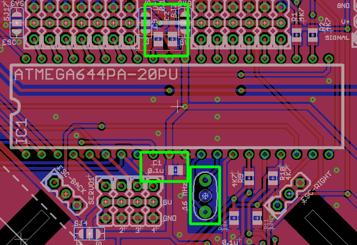
The ATmega644PA requires a 16 MHz resonator.
You must solder C1 and C2, which are 0.1 uF decoupling capacitors for the ATmega644PA. Also solder C9 which is a 0.1 uF decoupling capacitor for the analog reference.
On the bottom of the board, there is a footprint labelled "AREF-SEL", which allows you to choose the analog reference voltage by soldering over the pads labelled 5V or 3V3. You may also use a 0 ohm resistor here, or an ferrite bead. Note that AVCC is always connected to 5V.
Microcontroller Supporting Areas
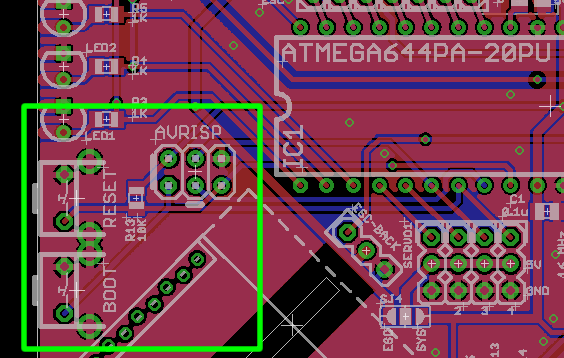
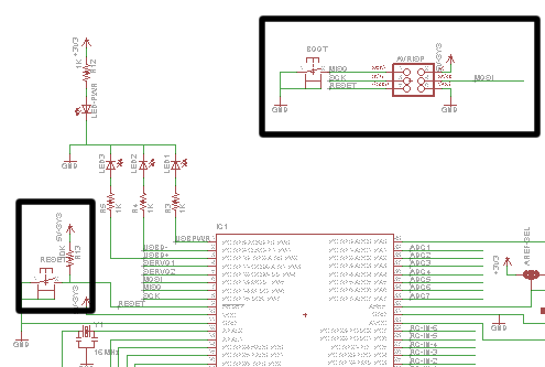
The reset switch must be installed, R13 10K ohm is the pull-up resistor for the reset switch. This resistor is optional because the ATmega644PA has a built-in pull-up resistor on the reset pin. You should install this if you do not trust the built-in resistor.
A push button labelled "BOOT" can be installed only if you are using a non-Arduino-standard bootloader. I personally hate the way "time sensitive" bootloaders work. This button is active low and connected to PB6 on the ATmega. Be sure to enable internal pull-up resistors for this button.
The ISP header (labelled AVRISP) should be installed if you need to use an AVR programmer (perhaps to load the bootloader for the first time, etc). The long line at the side indicates the side that the "red wire" (also pin 1) of the cable should be, and the short line at the bottom indicates where the notch of the connector should be.
LED Indicators
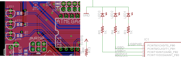
LED1, LED2, LED3 are 3 mm LEDs, choose your own colours. They can be mounted vertically or horizontally (pointing out). Please watch the polarity indicated by the hole shape and silkscreen. R3, R4, and R5, are all 1K ohm resistors to limit current to these LEDs.
Power Supply
Solder a LM1117 3V3 regulator in SOT-233-3 packaging where indicated on the PCB. Also solder the accompanying C3, which is 1 uF.
LED-PWR is a 3 mm LED that indicates that there is power present on the 3V3 supply bus. You may solder this vertically or sideways (pointing out). R12 is the 1K ohm current limiting resistor for this LED.
Two rows of 3 pin male headers should be installed at "3V3-TAP", these headers give you access to the 3V3 supply bus. Two rows of 3 pin male headers should be installed at "5V-TAP", these headers give you access to the "SYS" 5V supply bus.
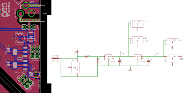
If you are powering this circuit from a battery, you must install a LM1117 5V regulator in SOT-233-3 packaging where indicated on the PCB. This may be omitted if you are using the ESCs as the power supply (be sure to set SJ1 correctly), or under other circumstances that you are under.
The 1 uF capacitor C4 should be always soldered regardless of whether or not you are using a 5V regulator.
The battery power input is used if you need to connect a battery. There are four ways to do this:
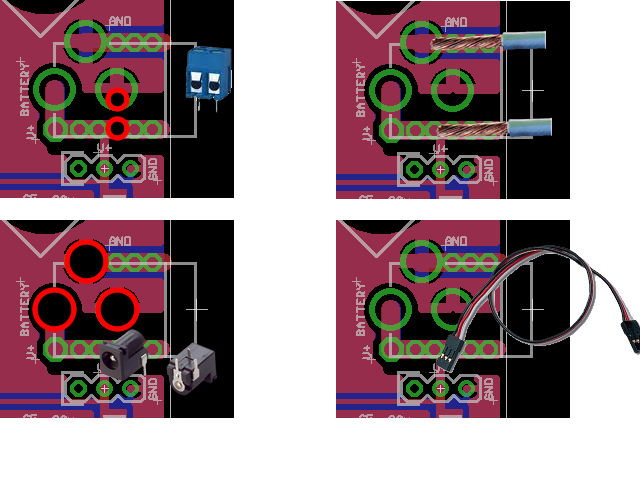
- Using a barrel jack
- Solder wire directly onto PCB (you can enlarge some holes to act as strain relief)
- using a screw terminal
- Using a 3 pin header
A beefy diode should be installed at D2 to protect the circuit from a battery connected backwards (so omit this diode if you believe in your own competence, you must bridge the pads of the diode footprint with solder if you omit this diode). This must be a diode that can handle 20V of reverse voltage, and handle 1.5A of forward current. The footprint is SMB or similar.
C5 and C6 are aluminum electrolytic 5.3mm x 5.3mm capacitors that must be installed, solder them in the correct orientation according to polarity.
RC Input
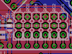
PORTC's pins PC7 to PC2 are connected to 6x3 headers, solder in male headers here. These are dedicated to taking RC pulse signals from your RC receiver. The voltage for the center pin can be connected to 5V or 3V3 using SJ2, and remember that there is a "5V-TAP" and "3V-TAP" if your receiver needs power from a 7th cable.
Important: If you select V-RC with SJ15 (to use the same voltage that the RC inputs are using) and you have selected 3V3 using SJ3, then you must not use SJ17 to select anything. Doing so will cause the 5V supply to be joined with the 3V3 supply, which can cause damage to 3V3 devices.
Sensors
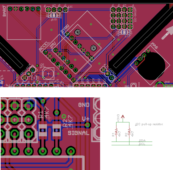
Solder R1 and R2, which are 4K7 pull-up resistors for the I2C bus. Be sure that you disable internal pull-up resistors in the software (note: already done for you in my modified software). This allows you to use 3V3 I2C sensors without using a level shifter.
Install a BMA180 accelerometer breakout board and a ITG-3200 gyro breakout board, both from SparkFun.
You may also choose to install a BMP085 barometric sensor breakout board, and a HMC5842 compass breakout board. These are optional and you can configure the software to use them for altitude-hold and compass-heading-hold.
Outputs to Motors and Servos
Four sets of 3-pin male headers should be soldered near "ESC" labels, these are connections for standard RC pulse signal ESCs. SJ1 can be used to connect the voltage supplied by the ESCs to the main system supply bus. (note, for this instructable, please connect SJ1)
Serial Ports
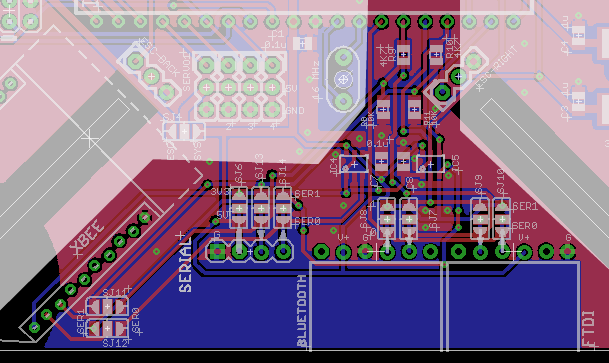
There are a few possible serial port devices. The ATmega644PA has two serial ports, USART0 and USART1, they are labelled SER0 and SER1 on the PCB.
Use horizontal mount male headers for the FTDI cable connection. This connection is always powered by 5V, RX and TX are at 5V level. Use SJ9 and SJ10 to decide whether to connect this to SER0 or SER1. (note, for this instructable, select SER0)
Part List
| Part | Other Attributes | Identifiers | Quantity Required | Example Product |
| ATmega644PA | 40 pin plastic DIP | IC1 | 1 | Digikey: ATMEGA644PA-PU-ND |
| 40 pin DIP socket | IC1 | 1 | Digikey: A411-ND | |
| 4K7 ohm resistor | 0805 or 0603 packaging, 1/16 W minimum | R1, R2, R9, R10 | 4 | Digikey: P4.7KACT-ND |
| 10K ohm resistor | 0805 or 0603 packaging, 1/16 W minimum | R8, R11, R13 | 3 | Digikey: P10KACT-ND |
| 15K ohm resistor | 0805 or 0603 packaging, 1/16 W minimum | R6 | 1 | Digikey: P15KACT-ND |
| 7K5 ohm resistor | 0805 or 0603 packaging, 1/16 W minimum | R7 | 1 | Digikey: P7.5KACT-ND |
| 1K ohm resistor | 0805 or 0603 packaging, 1/16 W minimum | R3-5, R12 | 4 | Digikey: P1.0KACT-ND |
| 1 uF capacitor | ceramic, 0805 or 0603 packaging, 16V rating minimum | C3, C4 | 2 | Digikey: 311-1358-1-ND |
| 0.1 uF capacitor | ceramic, 0805 or 0603 packaging, 16V rating minimum | C1, C2, C7, C8, C9 | 5 | Digikey: 311-1361-1-ND |
| 33 uF capacitor | electrolytic, 5.3 mm x 5.3 mm SMD aluminum can, 16V rating minimum | C5, C6 | 2 | Digikey: PCE3886CT-ND |
| 1N4148 diode | MELF packaging | D1 | 1 | Digikey: LL4148DICT-ND |
| Rectifier Diode | SMB packaging, 20V reverse voltage minimum, high forward current rating | D2 | 1 | Digikey: SSB44-E3/52TGICT-ND |
| 16 MHz resonator | Y1 (16 MHz on PCB) | 1 | SparkFun: COM-09420 | |
| Male headers | 0.1 inch pitch | ESC, I2C, I2C-GROUP, BARO, ACCEL, IMU, GYRO, MAG, BATTERY, BATT-MON, ADC1-7, RC1-6, 5V-TAP, 3V3-TAP, SERIAL, FTDI, maybe BLUETOOTH | Buy long strips and break them off | |
| 2x3 male headers | 0.1 inch pitch, no shroud allowed | AVRISP | 1 | Use the male headers you buy |
| TXB0101 bidirectional level shifter | SOT-23-6 package | IC4, IC5 | 2 | Digikey: 296-21664-1-ND |
| Tactile momentary push button switch SPST | Right angle, 7.50mm x 7.10mm | RESET, BOOT | 2 | Digikey: P12232SCT-ND |
| 5V regulator | SOT223, SOT-223-3 package | 5V-REG | 1 | LM1117MPX-5.0 |
| 3V3 regulator | SOT223 package | 3V3-REG | 1 | LM1117MPX-3.3 |
| LED | 3 mm, any colour | LED1-4 | 4 | SparkFun: COM-00533 |
| Barrel jack | Battery | 1 | SparkFun: PRT-00119 | |
| 2mm female pin headers | Xbee | 2 | SparkFun: PRT-08272 |
If you just want something that flies and don't care about the details, then just build the circuit and upload the code. If you want to know how I designed this circuit, continue reading this step.
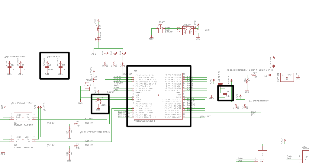
The first step is to draw out the circuit.
I started with the microcontroller. I knew it needed a reset button, a clock source (16 MHz ceramic resonator), a 6-pin header so I can program it with an AVR programmer, a serial port connection for the Arduino bootloader, and also 5V of power.
The sensors are connected to the I2C pins of the microcontroller. I2C busses require 4.7 kilo-ohm pull-up resistors to 3.3V to work. I can't use the ATmega's internal pull-up resistors because those go to 5V, which will damage the sensors.
The 3.3V voltage regulator is connected to the 5V power supply. Some capacitors are added in various spots to decouple and filter.
Connections to the RC radio receiver and the ESCs are simply male header pins connected to the microcontroller. The three pins are always "signal, +5V, ground".
This gave me a basic circuit. After, I alter it to add features such as indicator LEDs, solder-jumpers for configuration, xBee socket, etc.
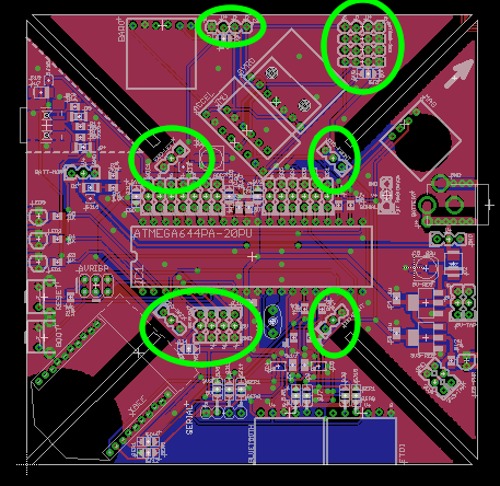
Laying out the PCB is also simple.
I start out with a square outline. Then I added slots to each corner of the square so I can mount it to any frame. Although I highly suggest you design the mounting hole patterns to suit whatever frame you get.
Next, I put down a ground plane on both sides.
The sensors needs to be placed in the correct orientation, as you can see, they are at a 45 degree angle.
The microcontroller is sort of the center piece. Header pins are placed where they are needed. The ESC pins are placed in each corner of the square to make them easy to identify later. The RC radio receiver input pins are placed in order to make them easy to connect. Any external connections such as the FTDI serial port are placed on the edge to make it easy to connect/disconnect. LEDs are also placed on the edge to make them more visible.
Remember that:
- Power rails might require a thicker trace on the PCB
- Avoid sharp corners
- Place capacitors physically close to the component they are meant for
- Label as much as possible
- Just because your PCB manufacture says they can do 6 mil trace thickness or clearance, doesn't mean you should try
- 0805 sized surface mount components have pads that are as big as through hole components, so to save space and weight, I suggest you use surface mount components. For the big ATmega644P, I used a through hole version because I wanted to use a chip socket so it's replacable.
Keep tweaking the design until you are ready for manufacturing the PCB. Export the Gerber files and send them to the manufacture. I usually use Seeed Studio who will make ten copies for $28 + shipping within 5 days + shipping.
Solder your circuit together and it should be good-to-go.


