

At first a few months ago I saw this Veear EasyVR speech recognition module, and I bought one on ebay because it looked pretty cool. When I got it I thought it might be a cool idea to control my room with it, and the idea was born to make my bedroom controlled by voice! But to make, for example, the lights work in voice I needed some relay function which reacts on my voice. So I thought a so called (in dutch) “Klikaan Klikuit” remote control set would work perfectly, it takes care of the dangerous things on playing with 230 volts, so I do not have to make a module or something for it. And the modules are pretty inexpensive, a set with a remote and 3 receivers costs 10 euro! The set I bought is shown below:

The idea was to control the remote control set with the EasyVR module, so there had to be an interface between those modules. I did read that the remote control set works at the 433MHz RF so I came up with the following interface:

The interface is pretty simple but one major point was to make sure I could duplicate the signals the remote of the remote control set was sending.
My approach to duplicate the signals was to read in the signals with my Logic Sniffer logic analyser which served me very good at this job!
I took apart the remote as seen below:


When I soldered the 3 wires (+ – and signal) I did connect it to my logic analyser, I also made a scratch at the RF signal out because otherwise the signal is shared with the 433MHz circuitry on the remote PCB.

This was actually a fun part because it all worked very well, I pushed the record button and pushed a button on the remote and the bits flew into the computer!
I have made a lot of pictures for explaining how you could do the same with a logic analyser and a certain RF or infrared device and then program it into a microcontroller.
The following procedure I used to capture the right signals and reverse engineer the protocol of the remote:
1. Approximately burst time measure
Sample at a pretty low sample-rate so you see a few whole bursts, as seen below. This way you make sure you got an idea of how long the actual burst is. In my case one burst is about 16ms (measure this). I the picture below you see some noise (the small burst) from the chip inside the remote, because we sample at a low sample-rate we can see that this small burst is not the right burst we’re looking for. For all steps we do you have to make sure you take multiple captures because it is possible you capture noise at some point, so look at the captures and take one where you see a result that you have seen on previous captures.

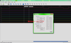
2. Exact burst time measure
Sample at a higher sample-rate so you can see exactly 1 whole burst. In the previous picture you see that there is a delay/time-out between the bursts, this makes you see when you have a whole burst. Also measure the whole burst so you know pretty accurate the whole burst time. See the picture below for an example of what I captured, the total time is 16,666 ms:

3. Bit time measure
Now its time to measure the bit time, this must be done as accurate as possible so we take an as high as possible sample-rate on which you can see 1 bit. See the picture below, I used a sample-rate of 5MHz which is pretty high, I knew from previous captures that my signal/burst begins with a long period high and then a small period low. From the whole burst picture I know that the small low period is the smallest time in the whole burst, so this must be my bit-time. I measured the low small period with a bittime of 171,4 μs. The long period was very near 3 times the measured bit-time, so in the picture below I see 3 bits high and then a low bit.
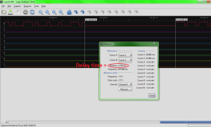
4. Measure the delay/time-out time
One very important thing to remember is the delay/time-out time. Because the receiver needs to receive a few bursts to make sure the signal is correct. In my case (and we will see this later in the code) I needed to send at least 3 bursts, with an exact time-out time of 5,328 ms (as seen in the picture below). The receiver measures or takes a nap during this period and verifies the bursts with this time-out period.
5. Check your measurements
This step just to check if we measured the signal/burst properly. We check the picture of step 2, the whole burst time and count the bits (bit time is 171,4 μs) we count 97 bits. To check our measurements and know we have a burst time of 16666μs (= 16,666 ms) and a bit time of 171,4 μs and divide the burst time by the bit time we should get a value which is near our 97 bits.
16666/171,4=97,23 bits
This is a value which is good enough for our purposes because the receiver module is a bit forgiving as we look at the bit time. It probably measures the bit state at the middle, or has some play in measuring the bit time. It is possible that our measurements are not 100% accurate and it is also possible that the sender is not totally correct and has a little tiny error in the crystal or oscillator.
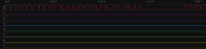
6. Reverse engineer the protocol
To reverse engineer the protocol I captured every button, in my case it where 10 buttons to push and compared the results. In the 2 pictures below you can see 2 buttons. I checked all the buttons and there was a difference only in the last bits so the data/command bits are stored in the last bits, the last 57 bits. This means the first 40 bits are start bits. At this point I have written the bit states down of all the 10 buttons with their 97 bits , I made a table to make it clear, this way I can program an array easily in the code later.
Remote A on:
Remote A off:

6. Make a clear picture of the protocol
Because we need to convert this burst/signal into code we need to have a clear picture of how the protocol works, below is a picture of the protocol:

Now we have all the information needed to control the receivers!
When I got all this information I thought it was a good idea to test it out. I bought a 433MHz transceiver set on ebay (433Mhz RF link kit for Arduino/ARM/MCU) which was cheap at about 5 dollar. I tested the 433MHz RF sender with the signal pin of the remote of the remote set and checked of it worked, and it did.
At this point I started to write code for the AVR ATtiny2313 I wanted to use, I wrote a test program which can be downloaded here.
The method I used for programming the burst into the microcontroller is to take a timer in the microcontroller and make sure the timer generates an interrupt every 171,4 μs (the bit time) at that exact interrupt it reads a bit out of an array (which consists of the burst) and sets a pin to that value.
This is actually a simple approach and it works fine.
Timing
To make a timer do this you have to set a compare value which generates the interrupt at the 171,4 μs. But we need to know what value this is, we can calculate this out of a few variables.
The value’s we know are:
-Microcontroller runs at 8MHz
-Bit time is 171,4 μs = 0,0001714 seconds.
This is the method for calculating the value of the register:
1. Calculate the clock cycle time of the microcontroller
The microcontroller runs at 8MHz, this means every clock cycle consists of 0,000000125 seconds. (1/8000000=0,000000125)
1. Calculate the register value
The clock cycle time is 0,000000125 seconds. If we divide the bit time by the clock cycle time we get 0,0001714/0,000000125=1371,2. The register only can contain a whole number so we take 1371. Now we have to decide what timer we want to use, we can chose a 8 or 16 bit timer. The 8 bit timer counts 256 clock cycles and the 16 bit timer counts to 65536. If I wanted to use the 8 bit timer I had to use the prescaler, this means that you divide the clock of the timer by a chosen number, check the datasheet. You can chose to divide by: none, 8, 64, 256, 1024. If we wanted to use the 8 bit timer you would have chosen to divide it by 8, but this makes it all a bit more inaccurate. So we chose to load a value of 1371 into the register.
In the code attached I loaded another value in the register because of inaccuracy of the internal oscillator, I measured it with my logic analyser and changed it until it was the right time.
Memory/optimization
Because we need to control 10 receivers with one microcontroller I needed to make the code as small as possible, the ATtiny2313 has enough memory, but we have to make smart code.
The 10 bursts we have to send all consists of 97 bits, this means we have to store 97 bits in an array. If we declare these bits as just bits we need an array of 97 for every burst. This is not very memory friendly because a microcontroller’s smallest memory is a byte, even when you declare a boolean it still takes a byte in memory.
To save memory I loaded 8 bits of the burst into a byte, this saves me 87,5% of memory! I wrote a piece of code to write the needed bit to the pin. For simplicity I declared 13 bytes (=104 bits), the burst consists of 97 bits but the programming gets a bit easier if we just can pick 13 whole bytes. The last 7 bits are zero’s so we can reduce the time-out time to make it all correct.
To save more flash memory we can store the arrays in the RAM memory, this is also done in the code.
Now we have done most of the coding work, the program is quite complete and easy to use. You can just call a function and it controls the pin and thus the 433MHz RF sender.
Now we have to use the EasyVR module to communicate with the microcontroller. This really easy to do because it works via serial communication. It’s not really necessary to explain it, there are datasheets and a lot of information about the module to find!
You can download the code for the whole project here.
Now I wrote the code and tested it all out I wanted to make a decent PCB for it so I could easily mount it to the wall or something and just leave it there. I also wanted to make it all work on a simple wall adapter. Below is the schematic I made, using Eagle:

Then I designed a PCB layout for it:

You can download the files schematic and board here.
How To Control Home Appliances by Your Voice


