Showing posts with label Electronic projects. Show all posts

Make own Heart Rate Monitor

I built a relatively simple heart rate monitor circuit that is monitored and controlled by an Arduino Uno. The theory of operation is based on the fact that infrared (IR) light is partially absorbed by blood. When your index finger is placed between the IR emitter and detector, the amount of IR light absorbed by the finger (and thus transmitted into the detector) varies in sync with your heart beat.
How to Make own Heart Rate Monitor,Make own Heart Rate Monitor,own Heart Rate Monitor,Heart Rate Monitor,Homemade Heart Rate Monitor,Heart Rate Monitor project

The Arduino monitors and filters the IR detector's signal, and turns a blue LED on and off in sync with your heart beat. The signal filtering library used by the Arduino code can be found here.
How to Make own Heart Rate Monitor,Make own Heart Rate Monitor,own Heart Rate Monitor,Heart Rate Monitor,Homemade Heart Rate Monitor,Heart Rate Monitor project
I also modified some Processing code that monitors and plots the filtered signal from the serial monitor.

heart_rate_signal.ino1 KB
Plot_Heart_Rate_Signal.pde2 KB

Step 1: Building the Circuit

Build the circuit shown. I used this emitter detector pair from SparkFun. The resistor in series with the emitter is 100 Ohm, and the resistor in series with the detector is 10 kOhm. I use a blue LED (right side of bread board) in series with a 100 Ohm resistor.

Step 2: Connections to the Arduino Uno

The 5 V pin on the Arduino powers both the IR emitter and detector. The Analog 0 input pin monitors the voltage after the 10 kOhm resistor, and the Analog 8 output pin controls the voltage on the blue LED.

Step 3: Output

First upload and run the Arduino code. Second, run the Processing code. The Processing code monitors the serial port output and plots it. The shape of the output pulses is very sensitive to how the index finger is placed between the emitter and detector (position, pressure, etc.), and you can see this in the video below as it's impossible to hold my index finger perfectly still for the duration of the video.

Update: On a whim, I removed the blue LED from the circuit and retested. The new video below shows a markedly improved heart rate signal. I'm not sure what kind of interference (optical? electrical?) was occurring with the Blue LED near the IR detector, but getting rid of it certainly improved the signal.

I'll continue testing but I'm curious to see what others find.

Read More

How to make a Virtual Reality 3D Tracking headset

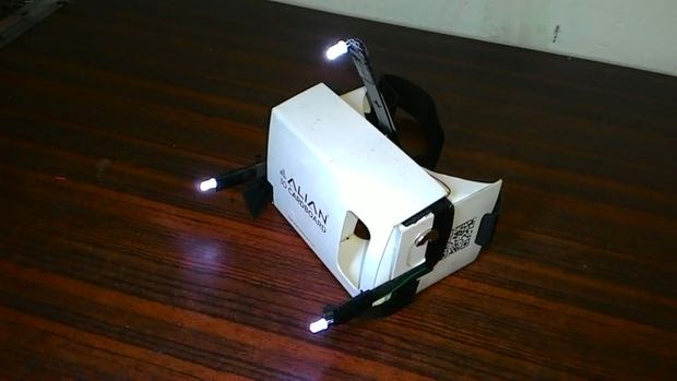
Picture of How to make a Virtual Reality 3D Tracking headset for under 10$


From the past 5 years, the increasingly popular Virtual reality devices like Oculus Rift, Google cardboard, Microsoft HoloLens, have currently dominated the consumer electronics sector to such extent that they much frequently grab a space in most tech magazines, blogs, websites,etc. With the collaboration of head-mounted displays/digital glasses and computer technology, these devices create a simulated, three-dimensional world that a user can manipulate and explore while feeling as if he were in that world.

This Instructable will guide you to make your very own virtual reality device which is very very much like the popular device Oculus rift which on the contrary costs 350$. The skills required for this device is pretty basic in tech and more basic in electronics. This device works with most Oculus rift games like Call of Duty, Silent hill, Flight simulator,etc and VR applications. So..Let`s get started!.........

Step 1: Items to grab...


  • An official/Unofficial cardboard headset - These headsets can purchased online fully assembled for 2-4 dollars like I did it else can be made at home for more cheap. The lens required for construction can be taken from any standard binoculars, the distance between the lens and the phone for display will be about 1.5 inch. For construction reference, see the pics.
  • 3 No. mid-size white LED
  • 3 No. 2-4 inch straight equal length sticks
  • A single 9 volt battery with a 5-10k resistor or 2 AA Batteries
  • 1-2 Ft. wire
  • Super glue/an quick adhesive

Home Items


  • 4.7-5.3 inch screen Android/IOS Phone
  • Laptop/Computer with Webcam

Downloads to do


And on to the construction........

Step 2: The circuit


Using the reference pic above build a simple circuit connecting the three LED to the Battery. You also can add a simple switch for convenience and solder joints for durability. Make sure to give adequate wire length on each LED to avoid future inconvenience.

Step 3: Attaching the sticks


Using glue, attach 2 equal length sticks parallel to each other on either side of the frame, allotting 1/4 length of the stick to be attached to the frame. Attach a third stick in a slanted 60 degree position half-way thru the top of the frame. Use adequate amount of glue for increased sturdiness and durability.

Step 4: Adding the LED circuit


With the help of tape and glue, firmly attach the three LEDs onto the end of the sticks, positioning them to face the front side of the headset. Using a stickpad/battery holder, attach the battery to one side of the headset that allows both circuit wire to reach the corresponding battery terminal easily. Tape the wires to the headset for durability and neatness.

Completing these finishes us off with the headset, now we`ll start work with our PC and mobile.

Step 5: Configure PC and Phone


Download and install the soft wares mentioned in step 1.


  1. Tridef 3D- TriDef 3D automatically converts DVDs, PC media files and photo files to 3D. You can play back originally made 3D content encoded in a variety of popular 3D formats – top/bottom, 2D plus depth and side by side. Play hundreds of the latest DirectX 9, 10 and 11 PC games, converted to 3D automatically. (*Note- During installation, select side-by-side 3D for the headset to work)
  2. FaceTrackNoIR- Modular headtracking program that supports multiple face-trackers, filters and game-protocols. Among the trackers are the SM FaceAPI, AIC Inertial Head Tracker and PointTracker (IR-tracker derived from FreeTrack). After installing, Select Game Protocol to Mouse Look and Tracker Source to PointTracker. For this program to work properly, you should sit in a well lit room with a good position so your webcam can track the LEDs easily within its range.
  3. KinoConsole- It is remote desktop application optimised for streaming games to your smartphone or tablet device. It basically mirrors PC display to an Android phone. Play games in windowed fullscreen mode for this to work.

Step 6: Testing


Follow the steps for a successful start up, First open FaceTrackNoIR and tweak settings as required. Different games has different setting so trial and error method have to be used sometimes. Then run Desktop streamer and the paired-up android app, after successful streaming to android screen run Tridef 3D. In Tridef 3D, browse a 3D game and launch through it. Slide your phone at the front of the headset with running streaming app. Turn on the LEDs and position yourself in-front of your webcam. Run the game in full screen windowed mode and tweak in game 3D settings for a smoother experience. Now you should be up and running.

Step 7: Finished

So by now the device should be up and running. Supporting hundreds of games it can set you off at cheap and easy.
Read More

How to Make Home Security System Using Mobile

2 Comments
The project is about a home security system in which a cell phone is used as a device that will alert the owner of the house when an intruder enters the house.
The owner just have to turn on the system before leaving his house.When an intruder enters the house in the absence of the owner the owner receives a call from a registered number which is the phone number of the hacked mobile phone at his/her house.

Now go to step and you need to do carefully :
  • Circuit Diagram :

Cell phones have switches which when pressed short the terminals (gold plated) hence a number is seen on the screen so what i have done is put my cell phone number on speed dial on the phone i hacked and when this number is pressed for a while i get a call.
So basically what we r doing is a circuit that will short the phone terminals. when a intruder enters the house.

IC LM358 is a dual op amp.

The output of an op amp is difference of the input times the gain of the op amp. ie. it compares the 2 inputs.

NOTE: Refer datasheet for ore details about the IC.

pin 2 of IC 358 is threshold a potentiometer is connected to it so it forms a voltage divider and a particular voltage is set up at pin 2 which the op amp compares with voltage at pin 3.

To pin 3 an LDR is connected it behaves in following way.

  1. When light shines on LDR its resistance decreases hence a more positive voltage is set up at pin 3 which forces the output to be high.hence there is a potential difference at the terminals of the number on the cell phone.
  2. When the light is cut off by the door which is opened by the intruder the LDR resistance increases hence a more negative voltage is set up at pin 3 which forces output to be low (0v).

In the equivalent op amp circuit shown Avid is approximately 0v when output is low and resistance Ro is very small hence the output is shorted to the ground thus shorting the 2 terminals of the cell phone.

  • Requirement :
  1. A Cellphone having press buttons (i used an old one which i had).
  2. A 10K ohm resistor.
  3. A 10K ohm potentiometer.
  4. An LDR (Light Dependent Resistor) 10K ohm or A 2 legged IR sensor (IR sensors are better bcoz they are not affected by surrounding light).
  5. An LM358 (Dual op-Amp) IC.
  6. An Optical LASER (I used a red LASER). In case you are using IR sensors use an IR LASER.
  7. Wires.
  • Do with your old mobile :
The cell phone i used is an old nokia phone.

Remove the battery then remove the front cover then the keypad an then the transparent cover over the keys.
You will see a thin white film on the key terminals dont worry just remove this film using a forceps but remember only cut the film on a key from 0 to 9. I just pulled it out in excitement and now i have problems starting the device i have to manually start it by shorting the terminals using any metallic object.
  • Check the polarities :
Insert the battery back into the cell phone and turn it on.

I wanted to use key 3 for the speed dial so i was checking the terminals on key 3.
Put a multimeter on dc voltage measurement then touch the probes to the 2 terminals on the key then reverse the probes on the key terminals either way the multimeter will show a reading but it will show +ve DC voltage when the probes are on correct -ve ,+ve terminals.

In my case the inner one was positive and the outer one negative.

Solder a red wire to the +ve terminal and a black wire to the -ve terminal.
  • Soldering the wires :
According to the circuit diagram solder the circuit.a small dotted board is enough as there are hardly any components.

NOTE: the circuit remains same if a 2 legged IR sensor is used.
Solder the red wire from the cell phone key to the output of the op-amp IC ie. at pin 1 and the black wire to the ground.
Solder the LDR to a small piece of board and solder wires to it (LDR does not have polarity so it can be connected any way to the main board).
  • Power Supply :
Use a cell phone charger just cut the jack and solder 2 wires to it which will be connected to the main circuit board.
  1. Red one is +ve (Vcc on circuit diagram).
  2. Black one is -ve (Ground on circuit diagram).
  • Placing the Circuit :
Place the sensor and LASER on opposite sides of a door.

focus the LASER on the Sensor such that LASER falls on the sensor when door is closed and it is cut off from the sensor when door is open.

Insert any sim card into the cell phone and register its number on your cell phone as 'security' or anything you like.insert the battery and turn the cell phone on.

turn on the power supply to the circuit.
  • Calibrating the circuit :


Read More

How to Control Arduino Robot using Android

I would like to explore the connection between Arduino and Android.
The goal here is to drive a small Arduino bot of the simplest kind with an Android app, through Bluetooth connection. The robot itself will have nothing extraordinary and is inspired by the many tutorials out there on the Interwebs.
But I have not found tutorials on how to create an Android remote control - so here it is simple steps to do its.
Step 1: All Materials


  • Arduino UNO or equivalent
  • Arduino-compatible 1A Motor Shield
  • 2x GM9 geared motors
  • 2x GMPV wheels
  • (optional) 2x mounting brackets
  • 1 ball caster
  • a 6 AA battery holder with 2.1mm jack
  • Bluetooth module (5€) such as this one on Ebay
  • 2mm MDF plate
  • some wires
  • some screws and nuts
  • a breadboard if you don't want to solder
  • 6 Alkaline AA batteries or 6 NiMh rechargeable batteries (they provide 7.5V instead of 9V, but this is still sufficient for the GM9 motors)
Step 2: Mounting  all electronics parts 


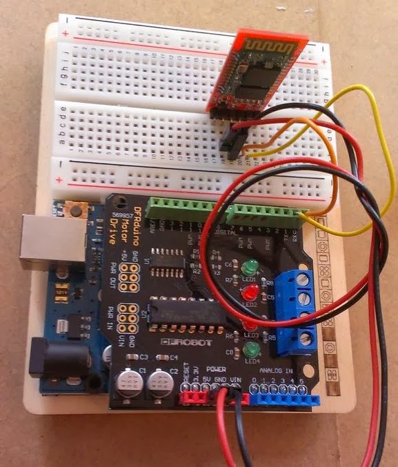
  • Mount the shield onto the UNO board. I assume your shield comes with soldered header. If not, you can find a nice picture on how to do it on this other instructable.
  • Mount the Bluetooth tranceiver on a breadboard.
  • Connect with wires the +5V and Ground from the Arduino board (actually, from the shield) to the +5V and Ground pins of the BT module
  • Connect with wires the Tx and Rx pins of the Arduino (ie, pins 0 and 1) to the Tx and Rx of the Bluetooth module.
Warning :
  • Some Bluetooth tutorials mention that you cross the connection (ie Tx to Rx and Rx to Tx). The way my module works, it needs to be parallel, ie Tx to Tx and Rx to Rx. You can try one way, and swap the connections if it doesn't work.
  • Remember to unplug the BT module while loading the script on the Arduino. The Tx and Rx plug are actually the same as the Serial port used to communicate with your computer through USB, and the BT module will mess up the communication.
Step 3: Prepare the motors

Solder wires on each motor electrodes. If one motor turns much slower than the other, it is likely due to poor soldering .
Step 4: Finish the assembly

  • Cut a piece of MDF - approximately 20x20cm
  • Mount the Arduino + shield on it as well as the battery pack on the MDF, as well as the ball caster on the back side. You can screw them or use double-sided tape
  • Mount the motors on each side of the MDF. Here again you can use tape or screws, but I chose to screw them for better stability
  • Connect the motors wires to the motor shield
  • That's it ! As you can see, it's a really simple robot layout.
Step 5 : Its Software time
  •  An Android app gives user the ability to connect to and disconnect from the bluetooth module. When connected, a serial link will exist between the smartphone and the Arduino robot
  • The user can then use arrows to drive the robot and a "stop" button to, well, stop it. Every time the user presses a button, the app sends a character (eg "f" for forward, "s" for stop and so on)
  • The Arduino board listens to the Serial port. When a character is received, it drives the motors accordingly.
Step 6: The Arduino sketch
Upload the attached code to the Arduino Uno. Remember, to unplug the bluetooth module while doing so.
Download the source code of arduino_for_android_remote
As you can see 5 intructions are defined : move forward, backwards, left, right, and stop. All motions are executed at full speed (the GM9 motors are geared, and thus not turning very fast) but you could change the speed value if you want. 
 Step 7: The Android App
 For Next Step you need to read next Post :
Control Your Robot Using Android Apps
Read More

How to make Smartphone Charger Powered By Fire


Hello Friends Now i am teaching you about electricity friendly charger .You can Charge you smartphone just by fire not by Electricity How cool isn't it.
Just follow below step to do that

First of all we know about concept behind it
I´m using a thermoelectic module, also called peltier element, TEC or TEG. You have one hot side and one cold. The temperature difference in the module will start producing electricity. The physical concept when you use it as a generator it's called the Seebeck effect. Thermoelectic modules are mainly used for the opposite effect, the Peltier effect. Then you apply a electric load and it will force a heat transfer from one side to the other. Often used in smaller refrigerators and coolers. 
For more follow below link : http://en.wikipedia.org/wiki/Thermoelectric_effect
Now go ahead to made them

DSC_4517.jpg

Step 1: Material Requirement
  • 1x high temperature TEG module: TEP1-1264-1.5
  • 2x voltage step-up 
  • 1x small heat sink. From old PC (BxWxH=60x57x36mm)
  • 1x Aluminum plate: BxWxH=90x90x6mm
  • 1x 5V brushless DC motor with plastic fan (could be hard to find, check this link)
  • Fixation for heat sink: Aluminum bar (6x10x82mm)
  • 2x M3 bolts+2nuts+2x washers for heat sink: 25mm long
  • 2x M3 1mm thick metal washers
  • 4x M4 bolts+8x nuts+4x washers as construction base: 70mm long
  • 4x M4 1mm thick metal washers
  • 4x M4 bolts: 15-20mm long
  • 4x Drywall screw (35mm)
  • 2x heat insulated washers: Constructed from cardboard and old plastic food turner
  • 80x80x2mm corrugated cardboard (Not very good at high temperatures)
  • 2x pull springs: 45mm extended
  • (Optional) Components for a temperature monitor and voltage limiter. 
Step 2: Construction of Base Plate
Now we need to arrange base plate as given figure show you.
DSC_4450.jpg

This will be the "hot side". It will also act as construction base plate to fixate heat sink and some legs.
  1. How you construct this depends on what heat sink you are using and how you want to fixate it.
  2. I started to drill two 2.5mm holes to match my fixation bar. 68mm between them and the position is matched of where I want to put the heat sink. Holes are then threaded as M3.
  3. Drill four 3.3mm holes at the corners (5x5mm from outer edge). Use a M4 tap for threading.
  4. Make some nice looking finishing. I used a rough file, a fine file and two types of sand paper to gradually make it shine! You could also polish it but it would be too sensitive to have outside.
  5. Screw the M4 bolts through the corner holes and lock it with two nuts and one washer per bolt plus the 1mm washer on the top side. Alternative one nut per bolt is enough as long as the holes are threaded. You can also use the short 20mm bolts, depends on what you will use as heat source.
Step 3: Construction of Heat Sink
Most important is to fixate the heat sink on top of the base plate but at the same time isolate the heat. You want to keep the heat sink as cooled as possible. The best solution I could came up with was two layers of heat insulated washers. That will block the heat from reaching the heat sink through the fixating bolts. It need to handle about 200-300ºC. I created my own but it would be better with a plastic bush like this. I could not find any with high temperature limit. The heat sink needs to be under high pressure to maximize the heat transfer through the module. Maybe M4 bolts would be better to handle higher force.
DSC_4445.jpg

  1. Modified (filed) aluminum bar to fit in the heat sink
  2. Drilled two 5mm holes (should not be in contact with bolts in order to isolate heat)
  3. Cut two washers (8x8x2mm) from old food turner (plastic with max temp of 220ºC)
  4. Cut two washers (8x8mmx0.5mm) from hard cardboard
  5. Drilled 3.3mm hole through plastic washers
  6. Drilled 4.5mm hole through cardboard washers
  7. Glued cardboard washers and plastic washers together (concentric holes)
  8. Glued plastic washers on top of aluminum bar (concentric holes)
  9. Put M3 bolts with metal washers through the holes (will later be screwed on top of aluminum plate)
Step 4: Assembly of Parts
  1. Mount TEG-module on heat sink.
  2. Place cardboard on heat sink and TEG-module is now temporally fixated.
  3. The two M3 bolts go through the aluminum bar and then through the cardboard with nuts on top.
  4. Mount heat sink with TEG and cardboard on base plate with two 1mm thick washers in between to separate cardboard from the "hot" base plate.
  5. The assembly order from top is bolt, washer, plastic washer, cardboard washer, aluminum bar, nut, 2mm cardboard, 1mm metal washer and base plate.
  6. Add 4x 1mm washers on the upper side of base plate to isolate cardboard from contact
DSC_4459.jpg

Step 5: Electronics Parts
The main idea was to have a regulated output voltage to charge or power different kind of gadgets. Since the TEG-module produce very low voltage (0-5V depending on heat source) I needed a good voltage step-up and regulator.
TEG_complete.png
 I wanted to build everything myself and therefore created a whole different project for this since it turned out to be very useful. The voltage step up is not powerful enough so I built two of them. One will power the 3-5V fan and one will power other electronics.
DSC_4467.jpg

Top and Bottom Side of PC Board
MCP6002_monitor&limiter_circuit.png

Step 6: Assembly of Electronics Part
The circuit boards will be placed around the motor and above the heat sink. Hopefully they will not get too warm.
DSC_4485.jpg
  1. Tape the motor to avoid shortcuts and to get better grip
  2. Glue the cards together so that they fit around the motor
  3. Place them around the motor and add two pull springs to hold it together
  4. Glue the USB connector somewhere (I did not find a good place, had to improvise with melted plastic)
  5. Connect all cards together according to my layout
  6. Connect the PT1000 thermal sensor as close as possible to the TEG-module (cold side). I placed it beneath the upper heat sink between the heat sink and cardboard, very close to the module. Make sure it has good contact! I used super glue that can handle 180ºC.
  7. I advise to test all circuits before connected to the TEG-module and start heating it
DSC_4488.jpg
You are now good to go!

Step 7: Test and See the Result
It is a bit delicate to get started. One candle for example is not enough to power the fan and soon enough the heat sink will get as warm as the bottom plate. When that happen it will produce nothing. It must be started quickly with for example four candles. 
DSC_4520.jpg
Then it produce enough power for the fan to start and can start cool off the heat sink. As long as the fan keeps running it will be enough air flow to get even higher output power, even higher fan RPM and even higher output to USB.


Read More

How to Control DC Motor using Bluetooth

In this project we will control a DC motor with a smartphone via bluetooth. This project is great to learn more about:
  1. DC motor
  2. Interfacing Arduino with your smartphone
  3. Bluetooth module
  4. L293D
6bluethumb.JPG 
  •  Step 1: Parts Required

IMG_0244.JPG
  1. 1x Arduino Uno
  2. 1x Bluetooth Module (for example: HC-05)
  3. 1x Smartphone (any Android will work)
  4. BlueTerm application
  5. 1x L293D IC
  6. 1x DC motor
  7. 1x Breadboard
  8. Jumper Cables
  • Step 2: Schematics and common mistakes
Screenshot from 2013-02-23 17:15:28.png
Two common mistakes:
-You need to remove the RX and TX cables when you’re uploading the sketch to your Arduino.
-Sometimes people connect the TX from the bluetooth module to the TX of the Arduino… that’s wrong and it won’t work. Make sure you connect it properly, the TX into RX and the RX into the TX.
Note:
If the HC-05 Bluetooth Module asks for a password, It's '1234'.
  • Step 3:  Now Audrino Coding
/*
* created by Rui Santos, http://randomnerdtutorials.wordpress.com
* Control DC motor with Smartphone via bluetooth
* 2013
*/
int motorPin1 = 3; // pin 2 on L293D IC
int motorPin2 = 4; // pin 7 on L293D IC
int enablePin = 5; // pin 1 on L293D IC
int state;
int flag=0; //makes sure that the serial only prints once the state

void setup() {
// sets the pins as outputs:
pinMode(motorPin1, OUTPUT);
pinMode(motorPin2, OUTPUT);
pinMode(enablePin, OUTPUT);
// sets enablePin high so that motor can turn on:
digitalWrite(enablePin, HIGH);
// initialize serial communication at 9600 bits per second:
Serial.begin(9600);
}

void loop() {
//if some date is sent, reads it and saves in state
if(Serial.available() > 0){
state = Serial.read();
flag=0;
}
// if the state is '0' the DC motor will turn off
if (state == '0') {
digitalWrite(motorPin1, LOW); // set pin 2 on L293D low
digitalWrite(motorPin2, LOW); // set pin 7 on L293D low
if(flag == 0){
Serial.println("Motor: off");
flag=1;
}
}
// if the state is '1' the motor will turn right
else if (state == '1') {
digitalWrite(motorPin1, LOW); // set pin 2 on L293D low
digitalWrite(motorPin2, HIGH); // set pin 7 on L293D high
if(flag == 0){
Serial.println("Motor: right");
flag=1;
}
}
// if the state is '2' the motor will turn left
else if (state == '2') {
digitalWrite(motorPin1, HIGH); // set pin 2 on L293D high
digitalWrite(motorPin2, LOW); // set pin 7 on L293D low
if(flag == 0){
Serial.println("Motor: left");
flag=1;
}
}
}
For the android communication with our bluetooth module I’ve used the BlueTerm app, It’s completely free, so you just need to go to “Play store” and download it. Then you just need to connect your smarthphone with the bluetooth module. Remember to remove the TX and RX cables. (you can see in youtube video below how that’s done).
  • Step 4: Now Connect all Products
IMG_0232.JPG 
I've only set 3 commands to control the DC motor:

    ’0′ – Turns off the DC motor
    ’1′ – DC motor rotates to right
    ’2′ – DC motor rotates to left

Demo:
Read More

Make own Android PS3 / Xbox360 Controller Mount

I go though how to Make own Android PS3 / Xbox360 Controller Mount. It's light, cheap, and does what it is designed to do really well. Basically, BEST. ANDROID. ACCESSORY. EVER.
This can also be adapted to fit other controllers and other Android devices.
Step 1
Materials
  • Nexus 7 Tablet - $200 
  • PS3 / Xbox controller - $50
  •  For the Mount
  •  1/8" dia x 48" Mild Steel Rod -$3 (OR 1/8" dia x 48" Copper Rod)
  •  48" of 1/8" MDPC Expandable Tubing - Comes in packs of 20' rolls for $7
ps3Parts.JPG

This is the stuff that people use to manage cables inside of computers. But you want to have a flexible tube that won't scratch your device.
  •  1/8" Heat Shrink Tubing - $2
For some grippy stuff and to clean up the ends.
 Tools:
  1. A big vice
  2.  bending tools
  3.  measuring tape
 Step 2
Bending for the Controller
IMG_0897.JPG

 The idea is to work from the middle out. Pick the shape that will work best with the controller and the device.
 As far as I can thing of there are two ways to attach the controller. By making a clamping U shape to across the back, facing up and across the front, facing toward the device. I'm doing the latter.
  1.  Bend in half with the end having a small radius. 0.5 to 1"
  2.   Create a V shape, this will act as a lock for the controller later. (This can be tricky)
  3.   Bend around the end of the controller and back to the front.
  4.   Create the opposite V at the end of that. (This V is slighter than the first one)
  5.   Position the end to be out of the way of the middle buttons on the controller and at the correct angle for the device.
 Step 3
Bending for the Device
 Starting from the two ends sticking out parallel from the controller part;
  1.  Bend outwards to make a BIG V
  2.  Measure the correct angle and distance to put the corners of the device inline with that V.
  3.   Bend up at those points to make the back.
  4.   Bend forward across the device.
  5.   Bend down to complete the mount
 At this point you should have a lot of extra metal rod. Just cut that off at the proper location and call it good.
 Step 4
Soft goods
 This is just a wire frame. You don't want to scratch your stuff. So take the MDPC tube and cover the entire length with it.
 Then add the heat shrink.
IMG_0907.JPG
 Good locations include:
  • -The bottom of the controller
  • -The bottom of the device
  • -The top of the device
 Then use a little bit of heat shrink to close off the metal ends showing.
 And your done! You might want to do a little manual bending to get it just right though. 
 In order to actually play games using the PS3 controller though, you will either have to play games that already are built for wired gamepads and then use a OTG usb cable
 OR
 Download the Sixaxis app from the app store and emulate the touch controls. This method really opens up gaming options!
 Go Play!
Read More

How To Make Electrically Heated Jacket


You either spend half an hour putting on 7 layers of clothing to go outside or you spend an hour freezing because the bus was late. The cheapest commercially available electrically heated jacket that I know of costs like $300, which I think is just plain stupid for a bunch of wire and a battery. In part 1 of this project, I will show you how to mod your existing clothes so that they can be electrically heated. If you have a laptop, you can actually pull this off completely for free! :)

So some theory first: An electric heater is basically a lot of electricity running through a wire to produce heat. To make a wire heat up, just apply a voltage across it. So to make a portable heater, you just need a battery, and some wire wrapped around whatever you want to heat.
But how will you ensure you don' t make the wire so damn hot it melts? How will you ensure you get enough heat generated for the mod to be useful? How will you ensure that your battery doesn't explode because you are drawing too much current? For EE n00bs, the two equations that are your friends in this mod are Volts = Current * Resistance, and Power = (Volts²) / Resistance. (V=IR and P=V²/R from now on).

Battery heated jacket

Let's say you have a 12v laptop battery that normally delivers 40W of power to your laptop. To make a 40W heater using this battery, you must choose wire of a certain resistance. From P=V²/R: 40=12²/R. Solving the equation tells you that you want a wire with 3.6 ohms of resistance to do the job. To get a wire of that much resistance, you've gotta find some pretty thin stuff. Forget about the good quality thick wires you connect your speaker system up with- they have almost 0 resistance. If you connect that stuff across your battery its going to blow up. Find a roll of the thinnest wire you can that is reasonably strong and isn't so stupidly thin its gonna melt just by farting on it. Now whip out your multimeter and cut the wire at whatever length gives 3.6ohms resistance. Now just connect this wire across your battery terminals, and you should instantly feel the wire heating up quite a lot.
Read More
Read More

How To Make Battery Powered universal USB Charger

This project details a small & simple, but very powerful USB charger for your mp3 player, camera, cell phone, and just about any other gadget you can plug into a USB port to charge! (See below for compatibility tests)

The charger circuitry and 2 AA batteries fit into an Altoids gum tin, and will run your iPod for hours! 2.5x more than you'd get from a 9V USB charger! (See Process for math/calculations) You can use rechargable batteries too.

universal usb battery charger


Parts list for v3.0

ImageNameDescriptionDistributor
Qty
IC1
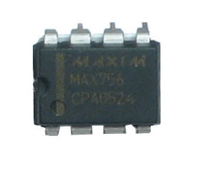
5V boost converter
LT1302CN8-5
Newark
Linear
1
IC1'
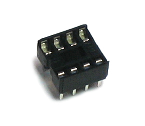
8-pin socketGeneric
1
C4, C3
Power supply capacitor
220uF/6.3V+
Generic
2
104 .1uf cerm
C1, C2
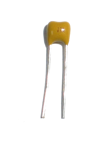
Bypass capacitor (0.1uF)Ceramic Capacitor
2
R5
1/8W 5% 3.3K resistor
Orange Orange Red Gold
This part was added in version 3.0. If you don't have one you may have a version 2.0 kit!
Generic1
R2, R41/8W 1% 75K resistor
Violet Green Black Red Brown
This part was added in version 3.0. If you don't have one you may have a version 2.0 kit!
2
R1, R31/8W 1% 49.9K resistor
Yellow White White Red Brown
This part was added in version 3.0. If you don't have one you may have a version 2.0 kit!
2
1N4001
D1
1N5818 (or 1N5817, etc) Schottky Diode1N5818
1
L1
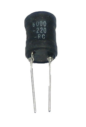
10uH power inductor, at least 1A current capabilityRLB9012-10
1
X1
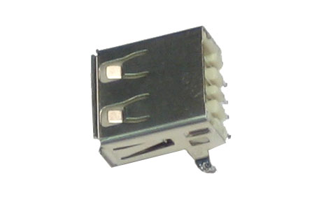
USB type A female jackGeneric
1
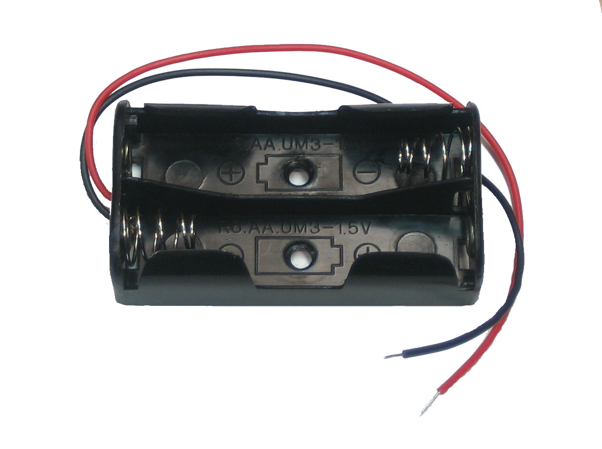
2 x AA battery holderKeystone 2463
1
PCB
Circuit boardAdafruit Industries
1


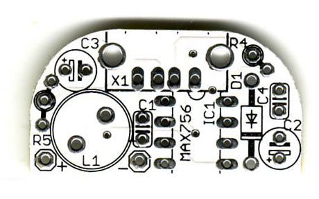
Circuit Diagram:


Specifications:

  • 5V output @ 500mA output
  • Recharges just about any gadget with a USB cable
  • Uses any AA batteries!
  • Upgrade to C or D cells for a mega battery pack
  • iPhone (all types): 3/4 full recharge
  • iPod video (tested, using alkaline batteries): 3hrs more video (1 full recharge)
  • iPod mini (tested w/rechargables): 26 hours more (1.5 full recharges)
  • iPod nano: 4 full recharges!
  • iPod shuffle : 60 hours more , 5 full recharges!

  • High efficiency power conversion is up to 83% efficiency, 2.5x more power than a 9V battery.
  • Plug in anything that charges via USB.

Read More