

Control your projects over the Internet or use data from a web page with the E-Net Module, an addon for the Propeller Platform.
The E-Net Module is an open source project which uses Microchip's ENC28J60 giving the Propeller Platform the ability to become an embedded webserver, IRC client, or even help you determine if you need to take an umbrella with you today.
The magic behind the E-Net Module is Harrison Pham's PropTCP which is an MIT licensed object.
This article will take you through the assembly of the E-Net Module as well as a couple projects which can be done with it.
Step 1Frequently Asked Questions

Frequently Asked Questions:
What is the E-Net Module?
It's an expansion module for the Propeller Platform, it lets you connect networks to your Propeller.
What does it work with?
It's set up to work the Parallax Propeller, it will fit on top of the Propeller platform, or you can drop it on a breadboard.
How many pins does it take?
The E-Net module takes four pins. There's space on the board to add two LED's, which will take two more pins, for a total of six. This leaves 25 pins open on the Propeller for the rest of your project.
Is it a webserver or a web client?
Either, depending on how you want to use it. It can serve web pages or data stored on an SD card, or query remote servers, parsing the response. I'll show you two demos, one parsing a web page for a weather report, and a second of a TV based IRC client
How much does it cost?
We make a kit for $33, or you can make your own - the expensive parts are the ENC28J60 chip ($4) and the pulsejack ($6), and the PCB (about $10, depending on how you get it made) We have included a schematic for those who want to assemble their own E-Net on a breadboard or PCB. Parts required for assembling your own E-Net Module can be sourced easily from here.
We have also provided the gerber files on the E-Net Module project page.
Step 2Example Project 1: Umbrella Alarm

After thinking about all the useful information that's sitting on the Internet, I re-wrote Rudolph to also grab data from web pages. You can get the code here.
Here's how to use it to grab a weather forecast off the Internet and remind you when to grab an umbrella;
1. Find the web page that has the data you want
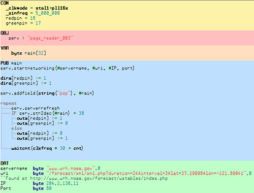
Small pages work best. For weather forecasts, I surfed around the NOAA site and found this page. This is what I entered;
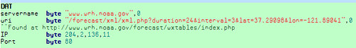
Start the networking with:
2. Identify the data you want to use
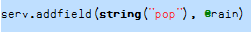
On that page, the data element <pop> is the probability of precipitation for my area. For my Umbrella Alarm, I don't need the whole page - just the value stored in the pair of <pop> tags. The
The first argument,
3. Grab the web page!
Now we know what web page our data is stored on, what data we want to retrieve, and where to store the result. serverrefresh grabs the page and updates the values. Each time we call it, a request is sent to the remote server and the local values are updated with whatever the server returns.
Keep in mind the result is always returned as a text string. If the result should be a number (like the probability of rain), the str2dec method will convert it to a number for you.
This umbrella alarm grabs a web page that includes a weather forecast, parses it and returns the probability of rain. If the probability of rain is greater than 30%, our red LED turns on. Here's the complete program;
Here's how to use it to grab a weather forecast off the Internet and remind you when to grab an umbrella;
1. Find the web page that has the data you want
Small pages work best. For weather forecasts, I surfed around the NOAA site and found this page. This is what I entered;
Start the networking with:
startnetworking(@servername, @uri, @IP, port)2. Identify the data you want to use
On that page, the data element <pop> is the probability of precipitation for my area. For my Umbrella Alarm, I don't need the whole page - just the value stored in the pair of <pop> tags. The
addfieldmethod is how you identify what parts of the page you want to use in your project. Grab the data between the first pair of <pop> tags with the line;The first argument,
string("pop"), tells the program that we're looking for data within the <pop> tag. The second argument, @rain, tells the program where the data it finds should be stored. The search always stops when it finds the first tag that matches the criteria.3. Grab the web page!
Now we know what web page our data is stored on, what data we want to retrieve, and where to store the result. serverrefresh grabs the page and updates the values. Each time we call it, a request is sent to the remote server and the local values are updated with whatever the server returns.
Keep in mind the result is always returned as a text string. If the result should be a number (like the probability of rain), the str2dec method will convert it to a number for you.
This umbrella alarm grabs a web page that includes a weather forecast, parses it and returns the probability of rain. If the probability of rain is greater than 30%, our red LED turns on. Here's the complete program;
Step 3Example Project 2: tvIRC client

Once you've got a working E-Net Module stacked on the Propeller Platform, why not take it up one more notch and add a ProtoPlus board to top! The ProtoPlus board provides both composite video and audio channel as well as a prototyping area to add other components.
Another project you can build with this combination is the tvIRC client:

You'll need to add a keyboard interface to the ProtoPlus. In my example I've added a small stick-on breadboard and some female connectors to the top of the board. This turns the ProtoPlus into a Propeller "experimenters board", handy for other projects when you are finished.
The keyboard breadboard circuit is created around the Parallax PS2 breakout: (see image 1)

Once you have a working ProtoPlus w/Keyboard interface download the tvIRC source and open tvirc.spin.
You'll need to edit lines 42,44, and 45. This information can be obtained from your computer's Command Prompt, typing ipconfig. Change the 192.168.1.X to match your network.

The ircserver and channel lines are currently set to log into the #propeller channel at irc.freenode.net.
Jump on the channel and join us!
Another project you can build with this combination is the tvIRC client:
You'll need to add a keyboard interface to the ProtoPlus. In my example I've added a small stick-on breadboard and some female connectors to the top of the board. This turns the ProtoPlus into a Propeller "experimenters board", handy for other projects when you are finished.
The keyboard breadboard circuit is created around the Parallax PS2 breakout: (see image 1)
Once you have a working ProtoPlus w/Keyboard interface download the tvIRC source and open tvirc.spin.
You'll need to edit lines 42,44, and 45. This information can be obtained from your computer's Command Prompt, typing ipconfig. Change the 192.168.1.X to match your network.
The ircserver and channel lines are currently set to log into the #propeller channel at irc.freenode.net.
Jump on the channel and join us!
Step 4Building the E-Net Module


Turn on your soldering iron and let it warm up.
When you dump out the kit on your desk, don't be overwhelmed by the number of parts. The most commonly used part are simple resistors and I'll take you step-by-step through the entire process.
Start by mount the blank PCB in a work-vise as shown.
When you dump out the kit on your desk, don't be overwhelmed by the number of parts. The most commonly used part are simple resistors and I'll take you step-by-step through the entire process.
Start by mount the blank PCB in a work-vise as shown.
Step 54x 47ohm resistors

Grab the 4x 47ohm resistors (Yellow - Violet - Black), and bend the leads like shown.

Step 7Soldering & trimming resistors


The next three steps we'll do repeatedly though the course of the build:
1) Spread the leads apart and flip the board over.
2) Heat up the hole and lead with your soldering iron for a second or two, then add a bit of solder..
3) Trim off the excess lead with your dikes.
1) Spread the leads apart and flip the board over.
2) Heat up the hole and lead with your soldering iron for a second or two, then add a bit of solder..
3) Trim off the excess lead with your dikes.
Step 82x 220ohm resistors

Add the 2x 220 ohm resistors (Red - Red - Brown) to R8 and R9. These limit the current to the LED's that are on the Ethernet jack.


Step 116x 1uf ceramic caps

With exception to some optional indicator LEDs, that's it for the resistors! Now we need to add the capacitors.
There are 6x .1uF ceramic caps, they go at C1, C2, C3, C4, C5, and C6.
Because these are ceramic caps, it doesn't matter which way they go.
There are 6x .1uF ceramic caps, they go at C1, C2, C3, C4, C5, and C6.
Because these are ceramic caps, it doesn't matter which way they go.
Step 122x 33pF ceramic caps

C8 and C9 are 33pF ceramic caps marked '33' on the outside.
Again, it doesn't matter which way they go.
Again, it doesn't matter which way they go.
Step 1347uF electrolytic cap.

The 47uF Electrolytic cap that goes at C7.
Important Note: The Electrolytic cap is polarized, the stripe on the can marks the negative lead, and the lead on
the opposite side is positive. The positive lead goes through the hole marked with a '+' on the PCB
Important Note: The Electrolytic cap is polarized, the stripe on the can marks the negative lead, and the lead on
the opposite side is positive. The positive lead goes through the hole marked with a '+' on the PCB
Step 14Adding the inductor

Add the inductor at L1. It looks like a regular wire with a gray metal ring around it.

Step 16Adding the 28pin DIP socket

Add the 28 Pin DIP Socket at U1. The notch on one end of the socket goes to the left, just as marked on the PCB.
Putting the socket in the right way will help to make sure you put the IC in the right way, too.
Putting the socket in the right way will help to make sure you put the IC in the right way, too.
Step 17Adding the PulseJack

Now, add the PulseJack at U2. There's only one way it can go in.
Flip over the board and solder each pin in, and fold out the metal tabs.
Flip over the board and solder each pin in, and fold out the metal tabs.
Step 18Adding the indicator LEDs


The kit includes a couple optional indicator LEDs and 2 more 220 ohm resistors.
Note polarity very clearly - on the LED; "The shorter lead goes through the square hole."
Note polarity very clearly - on the LED; "The shorter lead goes through the square hole."
Step 19Installing the ENC28J60 chip

Add the ENC28J60 to the socket. Note the notch goes to the left.


